


62 Barracuda 180 Product Manual, Rev. A
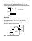
9.7.1.1 Single-ended drivers/receivers
The maximum total cable length allowed with drives using single-ended I/O driver and receiver circuits
depends on several factors. Table 16 lists the maximum lengths allowed for different configurations of drive
usage. These values are from the SPI-3 document. All device I/O lines must have equal to or less than 25 pf
capacitance to ground, measured at the beginning of the stub.
A stub length of no more than 0.1 meter (0.33 ft) is allowed off the mainline interconnection with any connected
equipment. The stub length is measured from the transceiver to the connection to the mainline SCSI bus.
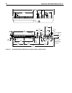
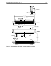
Single-ended I/O cable pin assignments for LW/LWV drives are shown in Table 13.
Single-ended I/O pin assignments for the LC/LCV models are shown in Table 14. The LC/LCV models do not
require an I/O cable—they are designed to connect directly to a back panel connector.
9.7.1.2 Low voltage differential I/O circuits
The maximum total cable length for use with drives using LVD I/O drivers and receiver circuits is 12 meters
(39.37 ft.). A stub length of no more than 0.1 meter is allowed off the mainline interconnection with any con-
nected equipment. LVD I/O pin assignments for LW/LWV model drives are shown in tables 12 and 13. LVD I/O
pin assignments for LC/LCV model drives are shown in tables 14 and 15.
9.7.1.3 General cable characteristics
A characteristic impedance of 100 ohm + 10% is recommended for unshielded flat or twisted pair ribbon cable.
However, most available cables have a somewhat lower characteristic impedance. To Minimize discontinuities
and signal reflections, cables of different impedances should not be used in the same bus. Implementations
may require tradeoffs in shielding effectiveness, cable length, the number of loads, transfer rates, and cost to
achieve satisfactory system operation. If shielded and unshielded cables are mixed within the same SCSI bus,
the effect of impedance mismatch must be carefully considered. Proper impedance matching is especially
important in order to maintain adequate margin at fast SCSI transfer rates.
9.8 Terminator requirements
Caution:
These drives do not have onboard internal terminators. The user, systems integrator or host equip-
ment manufacturer must provide a terminator arrangement external to the drive when termination is
required. For LW/LWV drives, terminator modules can be purchased that plug between the SCSI I/
O cable and the drive I/O connector or on the end of a short I/O cable stub extending past the last
cable connector. LC/LCV drives are designed to be plugged into a backpanel connector without
cabling.
9.9 Terminator power
LW/LWV drives
You can configure terminator power from the drive to the SCSI bus or have the host adaptor or other device
supply terminator power to the external terminator. See Section 8.1 for illustrations that show how to place
jumpers for this configuration.
LC/LCV drives
These drives cannot furnish terminator power because no conductors in the 80-pin I/O connector are devoted
to terminator power.
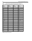
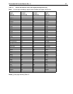
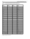
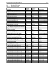
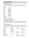
Table 16: Cable characteristics for single-ended circuits
I/O transfer rate
Maximum number of
devices on the bus
Maximum cable
length allowed
Transmission line impedance
REQ/ACK Other signals
<10M transfers/s 16 (wide SCSI bus) 6 meters (19.7 ft) 90 + 6 Ohms 90 + 10 Ohms
<
20M transfers/s 4 (wide SCSI bus) 3 meters (9.8 ft) 90 + 6 Ohms 90 + 10 Ohms
<
20M transfers/s 8 (wide SCSI bus) 1.5 meters (4.9 ft) 90 + 6 Ohms 90 + 10 Ohms