


SEAGATE ENTERPRISE PERFORMANCE 10K HDD V7 PRODUCT MANUAL, REV. C 20
6.3 DC POWER REQUIREMENTS
The voltage and current requirements for a single drive are shown below. Values indicated apply at the drive connector.
The standard drive models and the SED drive models have identical hardware, however the security and encryption portion
of the drive controller ASIC is enabled and functional in the SED models. This represents a small additional drain on the 5V
supply of about 30mA and a commensurate increase of about 150mW in power consumption. There is no additional drain on
the 12V supply.
[1] Measured with average reading DC ammeter. Instantaneous +12V current peaks will exceed these values. Power supply at nominal
voltage. N (number of drives tested) = 6, 35 Degrees C ambient.
[2] For +12 V, a –10% tolerance is allowed during initial spindle start but must return to ±5% before reaching 9,936 RPM. The ±5% must
be maintained after the drive signifies that its power-up sequence has been completed and that the drive is able to accept selection
by the host initiator.
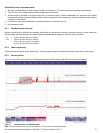
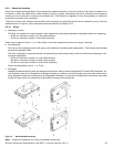
[3] See +12V current profile in Figure 1 (for 1200GB models).
[4] This condition occurs after OOB and Speed Negotiation completes but before the drive has received the Notify Spinup primitive.
[5] See paragraph 6.3.1, "Conducted noise immunity." Specified voltage tolerance includes, noise, and transient response.
[6] Operating condition is defined as random 8 block reads.
[7] During idle, the drive heads are relocated every 30 seconds to a random location within the band from three-quarters to maximum
track.
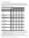
Table 1 1200GB standard drive DC power requirements
Notes
3.0Gb mode 6.0Gb mode
(Amps) (Amps) (Amps) (Amps)
Voltage +5V +12V [2] +5V +12V [2]
Regulation [5] ±5% ±5% [2] ±5% ±5% [2]
Avg idle current DC [1] [7] 0.32 0.25 0.33 0.25
Advanced Idle Current
Idle_A 3s 0.37 0.26 0.37 0.26
Idle_B 3s 0.28 0.21 0.28 0.22
Idle_C 3s 0.27 0.07 0.28 0.07
Standby 3s 0.26 0.01 0.26 0.01
Maximum starting current
(peak DC) DC 3s [3] 0.68 0.85 0.67 0.85
(peak AC) AC 3s [3] 1.02 1.60 0.85 1.52
Delayed motor start (max) DC 3s [1] [4] 0.26 0.01 0.27 0.01
Peak operating current (random read):
Typical DC [1] [6] 0.38 0.51 0.38 0.51
Maximum DC 3s [1] 0.43 0.53 0.42 0.53
Maximum (peak) DC 3s 1.57 1.52 1.62 1.51
Peak operating current (random write)
Typical DC [1] 0.39 0.49 0.40 0.49
Maximum DC 3s [1] 0.44 0.53 0.44 0.54
Maximum (peak) DC 3s 0.90 1.53 1.86 1.55
Peak operating current (sequential read)
Typical DC [1] 0.73 0.27 0.74 0.27
Maximum DC 3s [1] 0.81 0.29 0.80 0.29
Maximum (peak) DC 3s 1.00 0.62 1.01 0.61
Peak operating current (sequential write)
Typical DC [1] 0.57 0.31 0.58 0.31
Maximum DC 3s [1] 0.64 0.33 0.63 0.34
Maximum (peak) DC 3s 0.75 0.66 0.79 0.67