


P/N 21200027-001, Rev. B
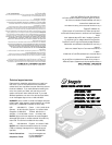
J2, Pin 1
50-Pin SCSI
Interface
SCSI Terminators
Remove in all but the last
drive in the chain
J5, Pin 1
4-Pin Power
Connector
1
2
3
4
HDA
Connector
Spin Sync
LED Driver
ID0
ID2
Disable
Spin
E1, Enable
Term Power
Disable
Spin
ID 2
ID1
ID0
J4
J3
J6
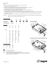
J2, Pin 1
50-Pin SCSI
Interface
E1..E3
E5 (Disable Spin)
E6 (Delay Spin)
E7 (Disable Parity)
E4
Reserved
SCSI Terminators
Remove in all but the last
drive in the chain
J4, Pin 1
4-Pin Power
Connector
1
2
3
4
HDA
Connector
Spin Sync
LED Driver
J3
J7
E8, Enable
Term Power In/Out
OE1
OE3
OE5, LED Driver
ST32105/32107/14207/N/W/WC/NV
INSTALLATION
Steps:
1. Turn off the computer and all attached peripheral equipment, such as printers and monitors.
2. Disconnect the AC power cable from the computer.
3. Remove the screws attaching the computer’s cover, and remove the cover from the system.
4. Remove the drive from the ESD (Electro Static Discharge) bag, carefully placing the drive on your work surface.
5. Configure the disk drive jumpers as necessary. Refer to table below for more details.
6. Remove SCSI terminator resitor packs (2) in all drives on the SCSI bus except for the last drive in the chain.
7. Remove and retain any hardware that may be attached to the selected bay.
8. Connect the cables; align the colored striped edge of the interface cable to pin 1 of the drive SCSI interface connector.
9. Partially insert the drive into the drive bay. Select an unused power connector from the power supply and connect it to the drive. If there are no unused
power connections on the power supply, you can purchase a “Y” cable adapter from your dealer. This connector will allow you to add another power
connection for your new drive.
10. Now that the drives are jumpered, connected, and have power cables attached, secure the drive or the mounting frame with four 6-32x.25 screws.
CAUTION: Do not use screws of excess length when attaching the drive. Damage to the drive’s circuit board could result. The maximum insertion in
bottom holes is .25”, the maximum insertion for side holes is .125”.
SCSI Disk Drive Models
Total Tables Jumper Warranty
Blocks LED Table Notes (Years)
ST31080N/WC 2,110,812 D a 2 5
ST32105N/W/WC 4,194,304 D b,c 1,2 5
ST32107N/W/WC/NV 4,194,304 D b,c 1,2 5
ST14207N/W/WC/NV 8,388,608 D b,c 1,2 5
Jumper Table
a ID0 ID1 ID2 N/A
b E1E2E3N/A
c OE1 OE2 OE3 N/A
SCSI ID
0 OUT OUT OUT OUT
1 IN OUT OUT OUT
2 OUT IN OUT OUT
3 IN IN OUT OUT
4 OUT OUT IN OUT
5 IN OUT IN OUT
6 OUT IN IN OUT
7 INININOUT
8 OUT OUT OUT IN
9 IN OUT OUT IN
10 OUT IN OUT IN
11 IN IN OUT IN
12 OUT OUT IN IN
13 IN OUT IN IN
14 OUT IN IN IN
15 IN IN IN IN
LED Configuration Table
Letter Connector LED+ LED-
B J-1 Pin 3 Pin 4
C J-5 Pin 3 Pin 4
D J-3 Pin 3 Pin 4
E J-7 Pin 1 Pin 2
Notes
Note 1 - “W” drives use Jumper Table c, e
Note 2 - “WC” drives have no jumpers
Note 3 - Parity is enabled by default. Install jumper E7 to disable parity.
Note 4 - Most SCSI host adapters are compatible with Seagate drives. Software drivers and installation
instructions are provided with the host adapter. Most drives are shipped with SCSI ID set to 6.
* - On some drives J5 may be replaced with an LED.
ST31080N/WC