


ST310014ACE Product Manual, Rev. D 19
2.1 Drive mounting
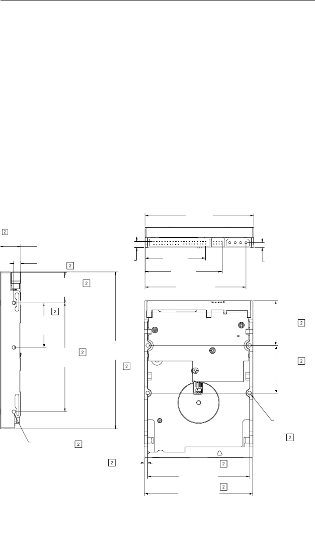
You can mount the drive in any orientation using four screws in the side-
mounting holes or four screws in the bottom-mounting holes. See Figure
3 for drive mounting dimensions. Follow these important mounting
precautions when mounting the drive:
• Allow a minimum clearance of 0.030 inches (0.76 mm) around the
entire perimeter of the drive for cooling.
• Use only 6-32 UNC mounting screws. Insert the screws no more than
0.20 inch (5.08 mm) into the bottom mounting holes and no more than
0.14 inch (3.55 mm) into the side mounting holes.
• Do not overtighten the mounting screws (maximum torque: 6 inch-lb).
• Do not use a drive interface cable that is more than 18 inches long.
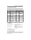
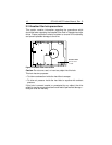
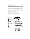
Figure 4. Mounting dimensions—top, side and end view
0.787 in. max
(19.99 mm)
0.250 in. max
(6.350 mm)
+0.024
–0.015
1.140 in.
+0.635
–0.381
(28.956 mm)
+0.025
–0.015
1.683 in.
+0.635
–0.381
(41.605 mm)
+0.025
–0.015
4.000 in.
+0.635
–0.381
(101.60 mm)
+0.015
–0.005
4.000 in.
+0.381
–0.127
(101.60 mm)
+0.015
–0.005
5.770 in.
+0.38
–0.13
(146.56 mm)
+0.020
–0.010
2X 1.750 in.
+0.508
–0.254
(44.450 mm)
+0.020
–0.010
2X 1.645 in.
+0.508
–0.254
(41.783 mm)
3X 6-32 UNC-2B
max. insertion depth
0.14 in. both sides
4X 6-32 UNC-2B
max. insertion dep
th
0.22 in.
0.125 in.
(3.175 mm)
0.226 in.
(5.750 mm)
4.000 in.
(101.600 mm)
2.229 in.
(56.616 mm)
2.829 in.
(71.856 mm)
3.717 ± 0.30 in.
(94.406 ± 0.762 mm)
0.176 ± 0.015 in.
(4.480 ± 0.381 mm)
3.750 ± 0.10 in.
(95.250 ± 0.254 mm)
Notes:
1. Dimensions are shown in inches (mm)
Dimensions are per SFF-8301 specification