


Barracuda LP Series SATA Product Manual, Rev. A 21
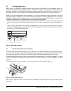
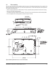
3.4 Drive mounting
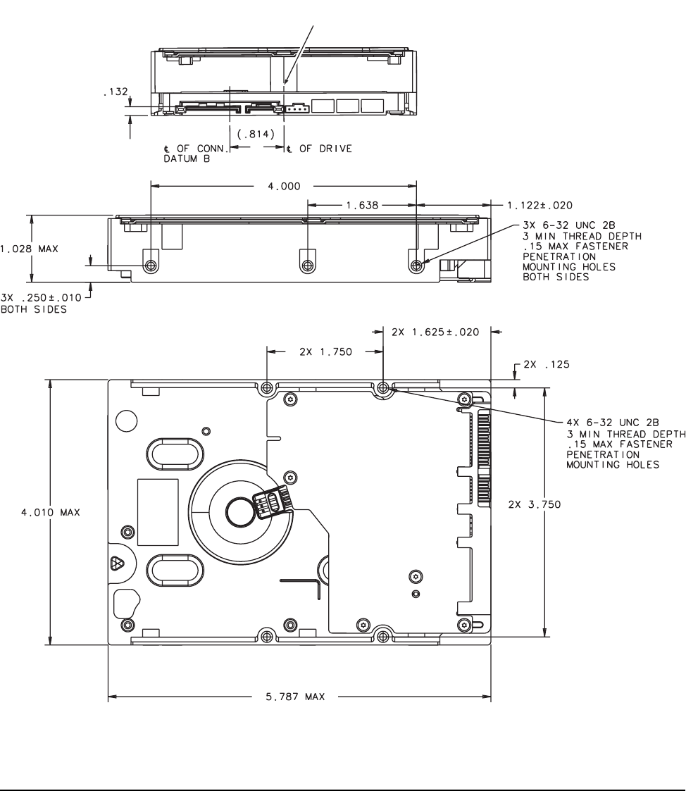
You can mount the drive in any orientation using four screws in the side-mounting holes or four screws in the
bottom-mounting holes. See Figure 5 for drive mounting dimensions. Follow these important mounting precau-
tions when mounting the drive:
• Allow a minimum clearance of 0.030 inches (0.76 mm) around the entire perimeter of the drive for cooling.
• Use only 6-32 UNC mounting screws.
• The screws should be inserted no more than 0.150 inch (3.81 mm) into the bottom or side mounting holes.
• Do not overtighten the mounting screws (maximum torque: 6 inch-lb).
Figure 5. Mounting dimensions (2.0, 1.5 and 1.0 TB models)
Recommended
case temperature
measurement location