


CONSTELLATION ES.2 SERIAL ATA PRODUCT MANUAL, REV. H 13
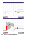
2.8.2 Conducted noise
Input noise ripple is measured at the host system power supply across an equivalent 80-ohm resistive load on the +12 V line or an
equivalent 15-ohm resistive load on the +5V line.
• Using 12V power, the drive is expected to operate with a maximum of 120mV peak-to-peak square-wave injected noise at
up to 10MHz.
• Using 5V power, the drive is expected to operate with a maximum of 100mV peak-to-peak square-wave injected noise at
up to 10MHz.
Note. Equivalent resistance is calculated by dividing the nominal voltage by the typical RMS read/write current.
2.8.3 Voltage tolerance
Voltage tolerance (including noise):
5V ± 5%
12V ± 5%
2.8.4 Power-management modes
The drive provides programmable power management to provide greater energy efficiency. In most systems, you can control power
management through the system setup program. The drive features the following power-management modes:
• Active mode
The drive is in Active mode during the read/write and seek operations.
• Idle mode
The buffer remains enabled, and the drive accepts all commands and returns to Active mode any time disc access is
necessary.
• Standby mode
The drive enters Standby mode when the host sends a Standby Immediate command. If the host has set the standby
timer, the drive can also enter Standby mode automatically after the drive has been inactive for a specifiable length of
time. The standby timer delay is established using a Standby or Idle command. In Standby mode, the drive buffer is
enabled, the heads are parked and the spindle is at rest. The drive accepts all commands and returns to Active mode any
time disc access is necessary.
• Sleep mode
The drive enters Sleep mode after receiving a Sleep command from the host. In Sleep mode, the drive buffer is disabled,
the heads are parked and the spindle is at rest. The drive leaves Sleep mode after it receives a Hard Reset or Soft Reset
from the host. After receiving a reset, the drive exits Sleep mode and enters Standby mode with all current translation
parameters intact.
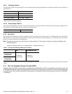
• Idle and Standby timers
Each time the drive performs an Active function (read, write or seek), the standby timer is reinitialized and begins count-
ing down from its specified delay times to zero. If the standby timer reaches zero before any drive activity is required, the
drive makes a transition to Standby mode. In both Idle and Standby mode, the drive accepts all commands and returns to
Active mode when disc access is necessary.
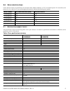
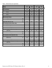
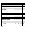
POWER MODES HEADS SPINDLE BUFFER
Active Tracking Rotating Enabled
Idle_a ID Biased Rotating Enabled
Idle_b Parked Rotating Enabled
Idle_c Parked Rotating at lower RPM Enabled
Standby Parked Stopped Enabled
Sleep Parked Stopped Disabled