6 ST320014A Product Manual, Rev. D
(such as track-to-track and average), are expected to meet or
exceed the noted values. However, due to the manner in which
these drives are formatted, benchmark tests that include com
-
mand overhead or measure logical seeks may produce results
that vary from these specifications.
1.7 Power specifications
The drive receives DC power (+5V or +12V) through a four-pin standard
drive power connector.
1.7.1 Power consumption
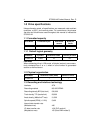
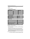
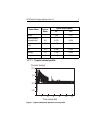
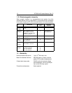
Power requirements for the drives are listed in the table on page 9.
Typical power measurements are based on an average of drives tested,
under nominal conditions, using 5.0V input voltage at 25°C ambient
temperature.
• Spinup power
Spinup power is measured from the time of power-on to the time that
the drive spindle reaches operating speed.
• Seek Mode
The read/write actuator arm moves in a random seek mode, with 80%
of the time spent seeking randomly among all the logical blocks, and
20% of the time idle. The current is measured over a 10-second period.
No data is read or written during this test.
• Read/Write power and current
Read/write power is measured with the heads on track, based on a
16-sector write followed by a 32-msec delay, then a 16-sector read
followed by a 32-msec delay.
• Operating power and current
The read/write actuator arm moves in a random read/write mode, with
80% of the time spent seeking, reading, and writing randomly among
all the logical blocks, and 20% of the time idle. The current is measured
over a 10-second period.
• Idle mode power
Idle mode power is measured with the drive up to speed, with servo
electronics active and with the heads in a random track location.
• Standby mode
During Standby mode, the drive accepts commands, but the drive is
not spinning, and the servo and read/write electronics are in power-
down mode.


