


58 Constellation ES.2 SAS Product Manual, Rev. D
12.4.2 Physical characteristics
This section defines physical inter
face connector.
12.4.3 Connector requirements
Contact your preferred connector manufacturer for matin
g part information. Part numbers for SAS connectors
will be provided in a future revision of this publication when production parts are available from major
connector manufacturers.
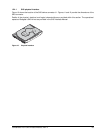
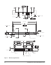
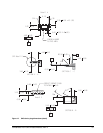
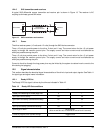
The SAS device connector is illustrated in Figures 11 and 12.
12.4.4 Electrical description
SAS drives use the device connector for:
• DC power
• SAS interface
• Activity LED
This connector is designed to either plug d
irectly into a backpanel or accept cables.
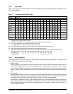
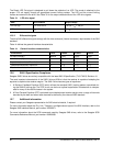
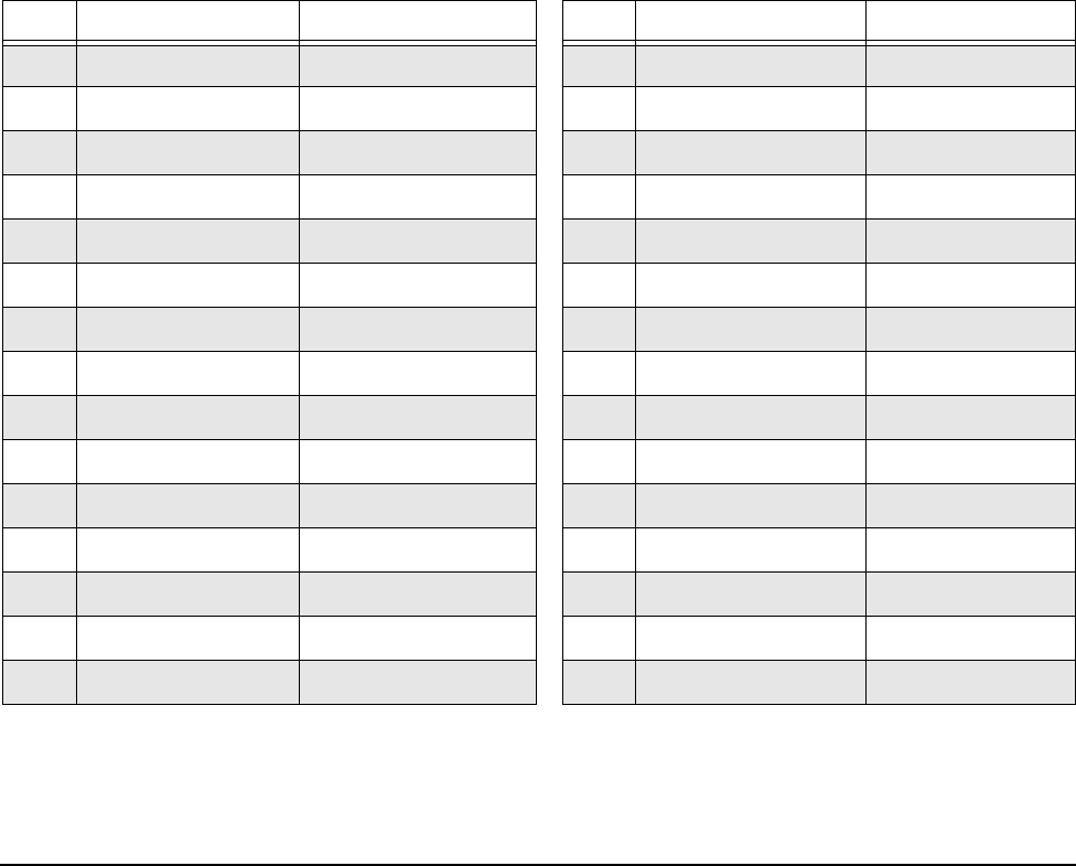
12.4.5 Pin descriptions
This section provides a pin-out of t
he SAS device and a description of the functions provided by the pins.
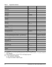
Table 11: SAS pin descriptions
Pin Signal name Signal type Pin Signal name Signal type
S1 Port A Ground P1* NC (reserved 3.3Volts)
S2* +Port A_in Diff. input pair P2* NC (reserved 3.3Volts)
S3* -Port A_in P3 NC (reserved 3.3Volts)
S4 Port A Ground P4 Ground
S5* -Port A_out Diff output pair P5 Ground
S6* +Port A_out P6 Ground
S7 Port A Ground P7 5 Volts charge
S8 Port B Ground P8* 5 Volts
S9* +Port B_in Diff. input pair P9* 5 Volts
S10* -Port B_in P10 Ground
S11 Port A Ground P11* Ready LED Open collector out
S12* -Port B_out Diff output pair P12 Ground
S13* +Port B_out P13 12 Volts charge
S14 Port B Ground P14* 12 Volts
P15* 12 Volts
* - Short pin to support hot plugging
NC - No connection in the drive.