


Cheetah 36XL Product Manual, Rev. E 73
Notes.
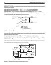
[1] See the
SCSI Interface Product Manual,
part number 75789509, Timing examples section.
[2] Maximum SCSI asynchronous interface transfer rate is given in Section 4.2.3 of this manual.
[3] Synchronous Transfer Period is determined by negotiations between an Initiator and a Drive. The Drive is
capable of setting periods as given in Section 9.5. See also the Synchronous data transfer section and the
Extended messages section of the
SCSI Interface Product Manual,
for a description of synchronous data
transfer operation.
9.11 Drive activity remote LED signal status
The following table provides drive activity remote LED signal status
Note. There is no drive activity LED mounted on the drive PCBA.
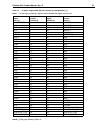
Data In Byte Transfer (parameter) T24 4.5-12 0.04 µs
Data Out Byte Transfer (parameter) T25 4.5-13 0.04 µs
Next Data In Byte Access (parameter) T26 4.5-12 0.12 µs
Next Data Out Byte Access (parameter) T27 4.5-13 0.12 µs
Data In Byte Transfer (media) [2] T28 4.5-12 0.04 µs
Data Out Byte Transfer (media) [2] T29 4.5-13 0.04 µs
Next Data In Byte access (media [2] T30 4.5-12 0.12 µs
Next Data Out Byte access (media [2] T31 4.5-13 0.12 µs
MSG IN Byte Transfer T32 4.5-5,7,8,14,15 0.04 µs
MSG OUT Byte Transfer T33 4.5-2 0.04 µs
STATUS Byte Transfer T34 4.5-5,8,15 0.04 µs
Synchronous Data Transfer Characteristics:
Request Signal Transfer Period [3] – – various (800 ns max)
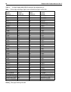
Table 19: Drive activity remote LED signal status
Spindle status Command status Remote LED signal status
Spinning up with DC power applied N/A On until spinup is complete
Spun down Start Unit On while processing the command
Powered down by removal of DC power N/A Off due to absence of power
Spun up Stop Unit On while processing the command
Spun down No command activity Off
Spun down Write/Read Buffer On while processing the command
Spun down SCSI Bus Reset On while processing the reset
Spun down Test Unit Ready On while processing the command
Spun up No command activity Off
Spun up Write/Read On while processing the command
Spun up SCSI Bus Reset On while processing the reset
Spun up Test Unit Ready On while processing the command
Spun up Format with Immediate option on On while the command is initially processed
Spun up Format without Immediate LED toggles on/off on each cylinder boundary
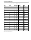
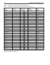
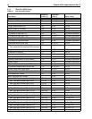
Table 18: Disc drive SCSI timing (Continued)
Description
Waveform
symbol [1]
Waveform
table [1] Typical timing