


Cheetah 15K.4 FC Product Manual, Rev. B v
List of Figures
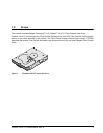
Figure 1. Cheetah 15K.4 FC family disc drive . . . . . . . . . . . . . . . . . . . . . . . . . . . . . . . . . . . . . . . . . . . . . 1
Figure 2. Typical ST3146954FC drive, 2 Gbit, +12V current profile . . . . . . . . . . . . . . . . . . . . . . . . . . . 28
Figure 3. Typical ST3146954FC drive, 2 Gbit, +5V current profile . . . . . . . . . . . . . . . . . . . . . . . . . . . . 28
Figure 4. Typical ST373554FC drive +12V current profile . . . . . . . . . . . . . . . . . . . . . . . . . . . . . . . . . . 29
Figure 5. Typical ST373554FC drive +5V current profile. . . . . . . . . . . . . . . . . . . . . . . . . . . . . . . . . . . . 29
Figure 6. Typical ST336854FC drive +12V current profile . . . . . . . . . . . . . . . . . . . . . . . . . . . . . . . . . . 30
Figure 7. Typical ST336854FC drive +5V current profile. . . . . . . . . . . . . . . . . . . . . . . . . . . . . . . . . . . . 30
Figure 8. ST3146954FC DC current and power vs. input/output operations per second . . . . . . . . . . . 31
Figure 9. ST373554FC DC current and power vs. input/output operations per second . . . . . . . . . . . . 32
Figure 10. ST336854FC DC current and power vs. input/output operations per second . . . . . . . . . . . . 33
Figure 11. Locations of the HDA temperature check point . . . . . . . . . . . . . . . . . . . . . . . . . . . . . . . . . . . 34
Figure 12. Recommended mounting . . . . . . . . . . . . . . . . . . . . . . . . . . . . . . . . . . . . . . . . . . . . . . . . . . . . 36
Figure 13. Mounting configuration dimensions . . . . . . . . . . . . . . . . . . . . . . . . . . . . . . . . . . . . . . . . . . . . 38
Figure 14. Physical interface . . . . . . . . . . . . . . . . . . . . . . . . . . . . . . . . . . . . . . . . . . . . . . . . . . . . . . . . . . 44
Figure 15. LED indicator connector . . . . . . . . . . . . . . . . . . . . . . . . . . . . . . . . . . . . . . . . . . . . . . . . . . . . . 44
Figure 16. Air flow . . . . . . . . . . . . . . . . . . . . . . . . . . . . . . . . . . . . . . . . . . . . . . . . . . . . . . . . . . . . . . . . . . 45
Figure 17. Physical interface . . . . . . . . . . . . . . . . . . . . . . . . . . . . . . . . . . . . . . . . . . . . . . . . . . . . . . . . . . 64
Figure 18. Port bypass circuit physical interconnect . . . . . . . . . . . . . . . . . . . . . . . . . . . . . . . . . . . . . . . . 64
Figure 19. FC-AL SCA device connector dimensions . . . . . . . . . . . . . . . . . . . . . . . . . . . . . . . . . . . . . . . 65
Figure 20. J6 connector dimensions . . . . . . . . . . . . . . . . . . . . . . . . . . . . . . . . . . . . . . . . . . . . . . . . . . . . 65
Figure 21. FC-AL transmitters and receivers . . . . . . . . . . . . . . . . . . . . . . . . . . . . . . . . . . . . . . . . . . . . . . 67
Figure 22. Transmit eye diagram . . . . . . . . . . . . . . . . . . . . . . . . . . . . . . . . . . . . . . . . . . . . . . . . . . . . . . . 72
Figure 23. Receive eye diagram . . . . . . . . . . . . . . . . . . . . . . . . . . . . . . . . . . . . . . . . . . . . . . . . . . . . . . . 73