


24 Barracuda 7200.7 Serial ATA Product Manual, Rev. N
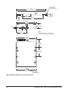
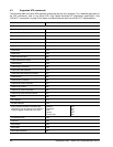
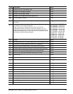
4.2 Serial ATA device plug connector pin definitions
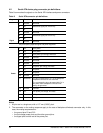
Table 8 summarizes the signals on the Serial ATA interface and power connectors.
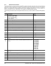
Notes:
1. All pins are in a single row, with a 1.27 mm (0.050”) pitch.
2. The comments on the mating sequence apply to the case of backplane blindmate connector only. In this
case, the mating sequences are:
• the ground pins P4 and P12.
• the pre-charge power pints and the other ground pins.
• the signal pins and the rest of the power pins.
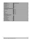
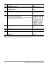
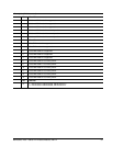
Table 8: Serial ATA connector pin definitions
Segment Pin Function Definition
Signal
S1 Ground 2nd mate
S2 A+ Differential signal pair A from Phy
S3 A-
S4 Ground 2nd mate
S5 B- Differential signal pair B from Phy
S6 B+
S7 Ground 2nd mate
Key and spacing separate signal and power segments
Power
P1 V
33
3.3V power
P2 V
33
3.3V power
P3 V
33
3.3V power, pre-charge, 2nd mate
P4 Ground 1st mate
P5 Ground 2nd mate
P6 Ground 2nd mate
P7 V
5
5V power, pre-charge, 2nd mate
P8 V
5
5V power
P9 V
5
5V power
P10 Ground 2nd mate
P11 Reserved The pin corresponding to P11 in the backplane
receptacle connector is also reserved
The corresponding pin to be mated with P11 in
the power cable receptacle connector shall
always be grounded
P12 Ground 1st mate.
P13 V
12
12V power, pre-charge, 2nd mate
P14 V
12
12V power
P15 V
12
12V power