


58
Cheetah NS SAS Product Manual, Rev. B
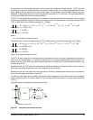
The leading and trailing edge slopes of figure 30 shall be preserved. As a result the amplitude value of Z1 is
less than that given in table 15 and Z1
TOL
and Z1
OP
shall be defined from those slopes by the following equa-
tion:
where:
Z1
TOL
is the value for Z1 to be used for the tolerance masks; and
Z1
OP
, X1
OP
, and X2
OP
are the values in table 15 for Z1, X1, and X2.
The X1 points in the receive tolerance masks are greater than the X1 points in the receive masks, due to the
addition of sinusoidal jitter.
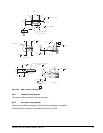
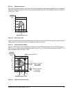
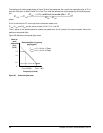
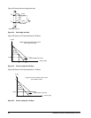
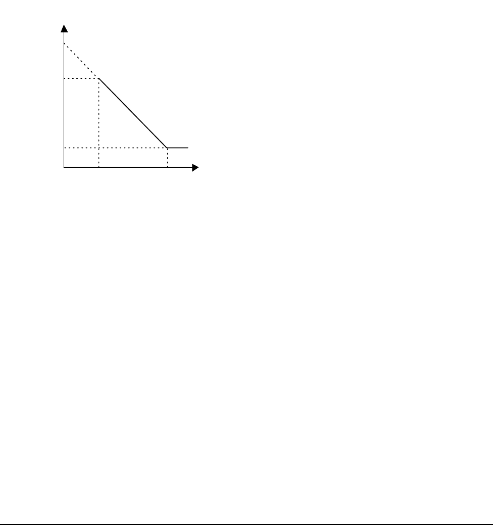
Figure 32 defines the sinusoidal jitter mask.
Figure 32. Sinusoidal jitter mask
Z1
TOL
Z1
OP
x
X2
OP
05,()xadditional sinusoidal jitter()– X1
OP
–
X2
OP
X1
OP
–
-----------------------------------------------------------------------------------------------------------------------------------=
F
NOM
/ 25,000 F
NOM
/ 1,667
Sinusoidal jitter frequency
(log/log plot)
Peak-to-
peak
sinusoidal
jitter
(in UI)
F
NOM
= 1.5 x 10
9
for 1.5 Gbps
F
NOM
= 3.0 x 10
9
for 3.0 Gbps
1.5
0
0.1
Frequency (in kHz)
1.0