


Barracuda 9LP Installation Guide, Rev. E 39
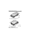
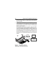
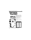
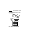
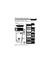
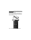
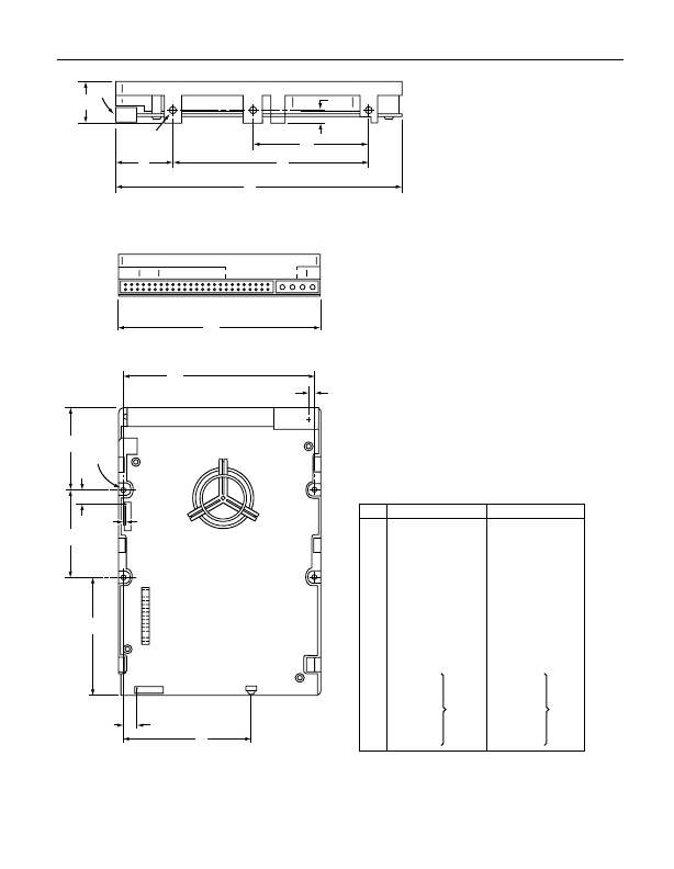
Figure 6. Mounting configuration dimensions
Inches
A
B
C
D
E
F
G
H
J
K
L
M
N
P
R
S
146.05
101.60
25.45
60.00
28.45
101.60
6.35
44.45
95.25
41.28
3.63
19.13
4.19
10.29
52.53
59.69
5.75
4.00
1.002
2.362
1.120
4.000
.250
1.750
3.750
1.625
.143
.753
.165
.405
2.265
2.350
± .025
± .015
+ .027
– .21
± .010
± .020
± .010
+ .010
– .005
± .010
± .010
± .020
± .64
± .38
+ .69
– .53
± .25
± .51
± .25
+ .25
– .12
± .25
± .25
± .51
Dimension Table
Millimeters
Mounting holes three on each side, 6-32 UNC. Max
screw length into side of drive 0.15 in. (3.81 mm).
Screw tightening torque 6.0 in-lb (.675 NM) max with
minimum thread engagement of 0.12 in. (3.05 mm).
Mounting holes four on bottom, 6-32 UNC. Max screw
length into bottom of drive 0.15 in. (3.81 mm). Screw
tightening torque 6.0 in-lb (.675 NM) max with minimum
thread engagement of 0.12 in. (3.05 mm).
Power and interface connectors can extend past the
“A” dimension by 0.040 in. (1.02 mm).
Centerline of pad for Pin 1 of power connector.
Centerline of pad for Pin 1 of J6.
Centerline of pad for Pin 1 of J2. Dimensions indicated
are for reference only.
Dimensions to Pin 1 of each connector are nominal
values.
To pin ends on J6. Pin ends on J6 are nominally flush
with end of drive.
Notes:
[1]
[2]
[3]
[4]
[5]
[6]
[7]
[8]
[7] [7]
F
D
A
E
[3]
C
G
[1]
B
J
[4] L
H
M [6]
[6] N
J2
J6 LED
K
S [8]
[2]
R
P [5]