


Hawk 1LP Family Installation Guide, Rev. D 33
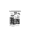
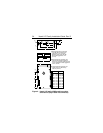
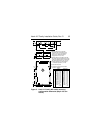
• Mount to host system chassis using four 6-32 UNC
screws. Three mounting holes are in each side and
four in the bottom of the drive. See Figure 4. The
maximum length that the screws should extend into
the side chassis mounting holes is 0.15 inch (3.81
mm), and 0.20 inch (5.1 mm) into bottom holes,
measured from the outer surface of the chassis. The
minimum thread engagement for all mounting screws
is .12 inch (3.0 mm). Tighten the screws evenly to a
maximum torque of 8 in-lb (.90 NM). Do not over
tighten or force when screw does not seem to screw
in easily (threads not correctly engaged).
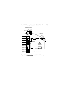
• Verify that all connections between the drive and the
host system are correctly installed. Most cables have
a contrasting color stripe indicating pin 1. Pin 1 on the
drive I/O connector and the DC power connector are
indicated in the figures in the Initial Set-up Informa-
tion section.
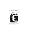
• Verify option select and drive ID select jumpers and
installation of terminator resistor packs where appli-
cable. See Drive Configuration section.