


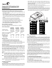
Figure 2. Option select jumpers (LW model only)
6. Mount the drive in the host system and connect cables
Note. LC drives are designed to be attached to a carrier or tray and
inserted into the host system without I/O or power cables.
a. Mount LW model drives to the host system’s chassis using four 6-32
UNC screws. Two mounting holes are in each side of the drive and
there are four mounting holes in the bottom of the drive. Do not over-
tighten or force the screws. You can mount the drive in any orientation.
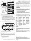
b. Connect the SCSI I/O cable into the drive’s SCSI connector. Take care
not to stretch or crimp this cable, and do not block the system’s cooling
air flow with the cable.
Note. For Ultra2 and faster operation, special twisted pair LVD cables are
required.
c. Connect the DC power cable to the drive. See Figure 3.
Figure 3. Cable connections and external termination
7. Format the drive
The drive has been low level formatted at the factory. You do not need to
perform another low level format on this drive unless you decide to perform
certain diagnostics through the host adapter. If you do decide to perform a
low level format, do not abort the format as this is likely to make the drive
inoperable. A low level format, with verify turned on, will typically take two
hours.
Protect against power failure or other power interruptions during the format.
a. Turn on DC power to the host system.
b. Boot the system from a system floppy, CD, or from a previously installed
hard disc drive if there is one.
c. Format the drive.
Caution. Formatting a drive erases all user data. Be sure that you under-
stand this principle before formatting any hard disc drive. It is not
necessary to format a drive that previously has been used to
store data, unless your intention is to erase all user data.
Seagate
®
is not responsible for lost user data.
Cheetah 10K.7 disc drives are designed to operate with a variety of operat-
ing systems. Please refer to your system or SCSI controller manual for
information about formatting and setting up the drive. Some quick desktop
system notes are provided below.
• Microsoft
TM
. Set the drive type in CMOS to “Zero,” “None,” or “No hard
drive installed.” Use FDISK.EXE and FORMAT.EXE. Systems using Win-
dows 98 or later can create one single partition (drive letter) on the drive.
• Macintosh
TM
. Use a third-party drive utility (most revisions of Apple’s HD
Setup utility only work with drives having special Apple firmware).
Troubleshooting
• Drive does not spin up. Check cables and all jumper settings. Make
sure cable pin 1 (edge stripe) matches PCB pin 1.
• Drive spins, but no LED on/off activity. Check SCSI ID setting. Set the
ID so that each device on the SCSI chain has its own unique ID. See also
the next item below. Host I/O controller is usually ID7.
• Computer does not seem to recognize the drive. Verify that the drive
is enabled by the SCSI host adapter setup utility.
• FDISK does not detect the drive. Run the FDISK program located on
your Windows startup diskette. Type fdisk/status to verify that your hard
drive is present.
Seagate support services
For online information about Seagate products, visit www.seagate.com or
e-mail your disc questions to DiscSupport@Seagate.com.
If you need help installing your drive, consult your dealer first. If you need
additional help, call a Seagate technical support specialist. Before calling,
note your system configuration and drive model number.
Africa +1-405-324-4714 Netherlands 00 800-47324283
Australia 1800-14-7201 New Zealand 0800-443988
Austria 0 800-20 12 90 Norway 00 800-47324283
Belgium 00 800-47324283 Poland 00 800-311 12 38
China* 800-810-9668 Spain 00 800-47324283
Denmark 00 800-47324283 Sweden 00 800-47324283
France 00 800-47324283 Switzerland 00 800-47324283
Germany 00 800-47324283 Singapore 800-1101-150
Hong Kong 800-90-0474 Taiwan* 00-800-0830-1730
Hong Kong† 001-800-0830-1730 Thailand 001-800-11-0032165
India 1-600-33-1104 Turkey 00 800-31 92 91 40
Indonesia 001-803-1-003-2165 United Kingdom 00 800-47324283
Ireland 00 800-47324283 USA/Canada/ 1-800 SEAGATE or
Italy 00 800-47324283 Latin America +1-405-324-4700
Japan 0034 800 400 554 Other European
Malaysia 1-800-80-2335 countries +1-405-324-4714
Middle East +1-405-324-4714
*Mandarin
†Cantonese
Warranty. Contact your place of purchase or our web site (above).
Return Merchandise Authorization (RMA). Before returning the drive, verify that it
is defective. Seagate Worldwide customer service centers are the only facilities autho-
rized to service Seagate drives. Contact nearest center for return procedures and trade
regulations.
Shipping the drive
Caution. Back up the data before shipping. Seagate assumes no responsibility for
data lost during shipping or service. Shipping drive in an unapproved container voids
the warranty. Pack the drive with original box and packing materials. Use no other
materials. This prevents electrical and physical damage in transit.
© 2004 Seagate Technology LLC All rights reserved
Publication number: 100260917, Rev. A, March 2004, Printed in U.S.A.
Seagate and Seagate Technology are registered trademarks of Seagate Technology
LLC. Cheetah and the Wave logo are registered trademarks or trademarks of Seagate
Technology LLC. Other product names are registered trademarks or trademarks of
their owners. Seagate reserves the right to change, without notice, product offerings or
specifications.
Enable parity check of SCSI bus.
Disable parity check.
J2
Pin 1
Reserved Positions
Parity Check option
Single-ended I/O
Terminator Power
Write protect = Off (enables writing).
Write protect = On (disables writing).
Write Protect option
Disable the Delay Motor Start option.
Motor start delay equal to the
SCSI ID multiplied by 12 seconds.
Delay Motor Start option (valid
only if the Enable Motor Start
jumper is not connected)
Enable motor start. The drive waits for
the Start Unit command from the host
before starting the spindle motor.
Disable motor start (default). The
drive starts according to the Delay
Motor Start option.
Motor Start option
Pin 1
End
SCSI I/O
Connector
Drive with
HDA up, PCB
down, viewed
from front
Pin 1
DC Power
Connector
J2
Drive Front
J6
Pin 1
HDA
J6
A
2
A
3
A
1
A
0
Reserved
Remote
LED
L
E
D
R
E
S
Reserved
Shipped with cover installed.
Do not remove.
Do not install jumpers
on these four positions.
J6 Jumper
CATH
11
12
J2 Jumper
(default)
(default)
(default)
(default)
A jumper here forces single-ended
I/O operation.
No jumper allows host to select either
single-ended or LVD operation.
Host adapter or other device provides
term. power to external terminator.
Term. Power to SCSI Bus
(default)
(default)
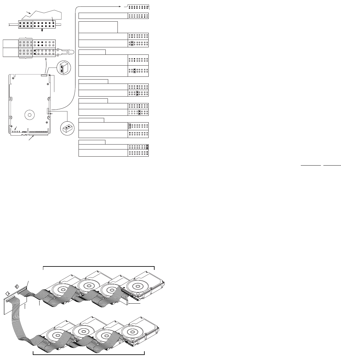
Pin 1
(check your
adapter for
Pin 1 location)
Host
Adapter
PCB
Twisted Pair
LVD Cable
Ultra160 or Ultra2 LVD bus segment
SPI-2 compliant
active LVD
external terminat
or
on the end of
the cable
SCSI LVD/SE
S
CSI SE
Ultra SCSI SE bus segment