


24
DB35.3 Series SATA/PATA Product Manual, Rev. F
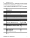
4.1 Serial ATA (SATA) interface
These drives use the industry-standard Serial ATA interface that supports FIS data transfers. It supports ATA
programmed input/output (PIO) modes 0–4; multiword DMA modes 0–2, and Ultra DMA modes 0–6.
For detailed information about the Serial ATA interface, refer to the “Serial ATA: High Speed Serialized AT
Attachment” specification.
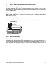
4.1.1 Hot-Plug compatibility
DB35.3 Series drives incorporate connectors which enable you to hot plug these drives in accordance with the
Serial ATA II: Extension to Serial ATA 1.0a specification. This specification can be downloaded from www.seri-
alata.org.
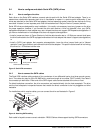
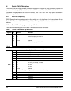
4.1.2 Serial ATA device plug connector pin definitions
Table 5 summarizes the signals on the Serial ATA interface and power connectors.
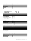
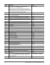
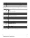
Table 5: Serial ATA connector pin definitions
Segment Pin Function Definition
Signal
S1 Ground 2nd mate
S2 A+ Differential signal pair A from Phy
S3 A-
S4 Ground 2nd mate
S5 B- Differential signal pair B from Phy
S6 B+
S7 Ground 2nd mate
Key and spacing separate signal and power segments
Power
P1 V
33
3.3V power
P2 V
33
3.3V power
P3 V
33
3.3V power, pre-charge, 2nd mate
P4 Ground 1st mate
P5 Ground 2nd mate
P6 Ground 2nd mate
P7 V
5
5V power, pre-charge, 2nd mate
P8 V
5
5V power
P9 V
5
5V power
P10 Ground 2nd mate
P11 Ground or LED signal If grounded, drive does not use deferred spin
P12 Ground 1st mate.
P13 V
12
12V power, pre-charge, 2nd mate
P14 V
12
12V power
P15 V
12
12V power