


Barracuda 18LP FC Installation Guide, Rev. A 21
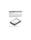
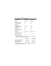
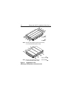
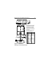
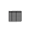
Figure 3: Dimensions
Abbildung 3: Laufwerkabmessungen
5.75
4.00
1.026
.620
4.000
.250
3.750
2.380
1.750
0.181
1.622
1.620
.1215
.1215
146.05
101.6
26.060
15.748
101.600
6.350
95.25
60.45
44.450
4.590
41.20
41.150
3.080
3.080
A
B
C
D
E
F
H
J
K
L
M
N
P
R
±
±
max
ref
±
+
–
±
±
±
+
–
+
–
±
max
max
0.025
0.015
0.010
0.011
0.005
0.010
0.010
0.010
0.013
0.007
0.027
0.021
0.025
± .64
± .381
max
ref
± .25
+ .28
– .12
± .25
± .25
± .50
+ .33
– .18
+ .69
– .53
± .64
max
max
Notes:
[1]
[2]
[3]
[4]
Inches Millimeters
Mounting holes three on each side,
6-32 UNC. Max screw length into
side of drive is 0.15 in. (3.81 mm).
Mounting holes four on bottom,
6-32 UNC. Max screw length into
bottom of drive is 0.15 in. (3.81 mm).
Keep-out zone for any components
on backplane.
Connector is centered on module
and flush with end of base.
A
F
D
E
C
M
L
[1]
[4]
Pin 1
Motherboard Ref.
H
1.875±.0051.875±.005
B
K
N
.136
J
[2]
Common centerline
in the horizontal
(X axis) direction
of the drive
Low
Profile
Half
Height
(.809)
R[3]
P