


Seagate Desktop HDD Product Manual, Rev. F 17
www.seagate.com Configuring and Mounting the Drive
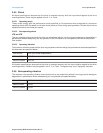
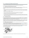
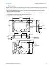
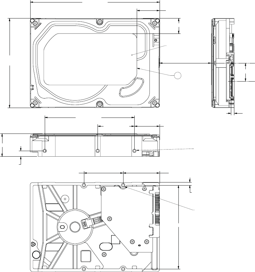
3.4 Drive mounting
Users can mount the drive in any orientation using four screws in the side-mounting holes or four screws in the
bottom-mounting holes. Refer to Figure 2 for drive mounting dimensions. Follow these important mounting
precautions when mounting the drive:
• Allow a minimum clearance of 0.030 inches (0.76mm) around the entire perimeter of the drive for cooling.
• Use only 6-32 UNC mounting screws.
• The screws should be inserted no more than 0.150 inch (3.81mm) into the bottom or side mounting holes.
• Do not overtighten the mounting screws (maximum torque: 6 inch-lb).
Figure 2 Mounting dimensions (3TB and 4TB)
TOP OF LABEL
5 TYP
3X 6-32 UNC-2B
3 MINIMUM THREAD DEPTH
0.15 MAXIMUM FASTENER
PENETRATION BOTH SIDES
4X 6-32 UNC-2B
3 MINIMUM THREAD DEPTH
0.15 MAXIMUM FASTENER
PENETRATION
C
L
OF DRIVE
C
L
OF CONNECTOR
DATUM B
5.787 in max
146.99 mm
4.010 in max
101.85 mm
2x 1.625 ± .020 in
41.28 ± .51 mm
2x 1.750 in
44.45 mm
2x 0.125 in
3.18 mm
4.00 in
101.60 mm
1.638 in
41.61 mm
1.22 ± .020 in
30.99 ± .51 mm
0.138 in
3.51 mm
0.814 in
20.68 mm
1.028 in max
26.11 mm
3x 0.250 ± .010 in
6.35 ± .25 mm
BOTH SIDES
2x 3.750 in
95.25 mm
1.013 ± .050 in
25.73 ± 1.27 mm
0.680 ± .050 in
17.27 ± 1.27 mm
TEMPERATURE
CHECK POINT