


Seagate Surveillance HDD Product Manual, Rev. A 18
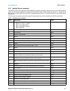
4.2 SATA device plug connector pin definitions
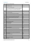
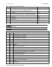
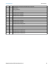
Table 5 summarizes the signals on the SATA interface and power connectors.
Notes
1. All pins are in a single row, with a 1.27 mm (0.050 in) pitch.
2. The comments on the mating sequence apply to the case of backplane blindmate connector only. In this
case, the mating sequences are:
• the ground pins P4 and P12.
• the pre-charge power pins and the other ground pins.
• the signal pins and the rest of the power pins.
3. There are three power pins for each voltage. One pin from each voltage is used for pre-charge when installed
in a blind-mate backplane configuration.
• All used voltage pins (V
x
) must be terminated.
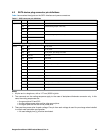
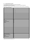
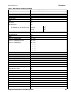
Table 5 SATA connector pin definitions
Segment Pin Function Definition
Signal S1 Ground 2nd mate
S2 A+ Differential signal pair A from Phy
S3 A-
S4 Ground 2nd mate
S5 B- Differential signal pair B from Phy
S6 B+
S7 Ground 2nd mate
Key and spacing separate signal and power segments
Power P1
V
33
3.3V power
P2
V
33
3.3V power
P3
V
33
3.3V power, pre-charge, 2nd mate
P4 Ground 1st mate
P5 Ground 2nd mate
P6 Ground 2nd mate
P7
V
5
5V power, pre-charge, 2nd mate
P8
V
5
5V power
P9
V
5
5V power
P10 Ground 2nd mate
P11 Ground or LED signal If grounded, drive does not use deferred spin
P12 Ground 1st mate.
P13
V
12
12V power, pre-charge, 2nd mate
P14
V
12
12V power
P15
V
12
12V power