


SEAGATE LAPTOP THIN SSHD SATA PRODUCT MANUAL, REV. D 16
CONFIGURING AND MOUNTING THE DRIVE
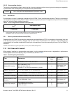
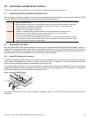
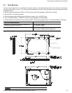
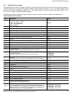
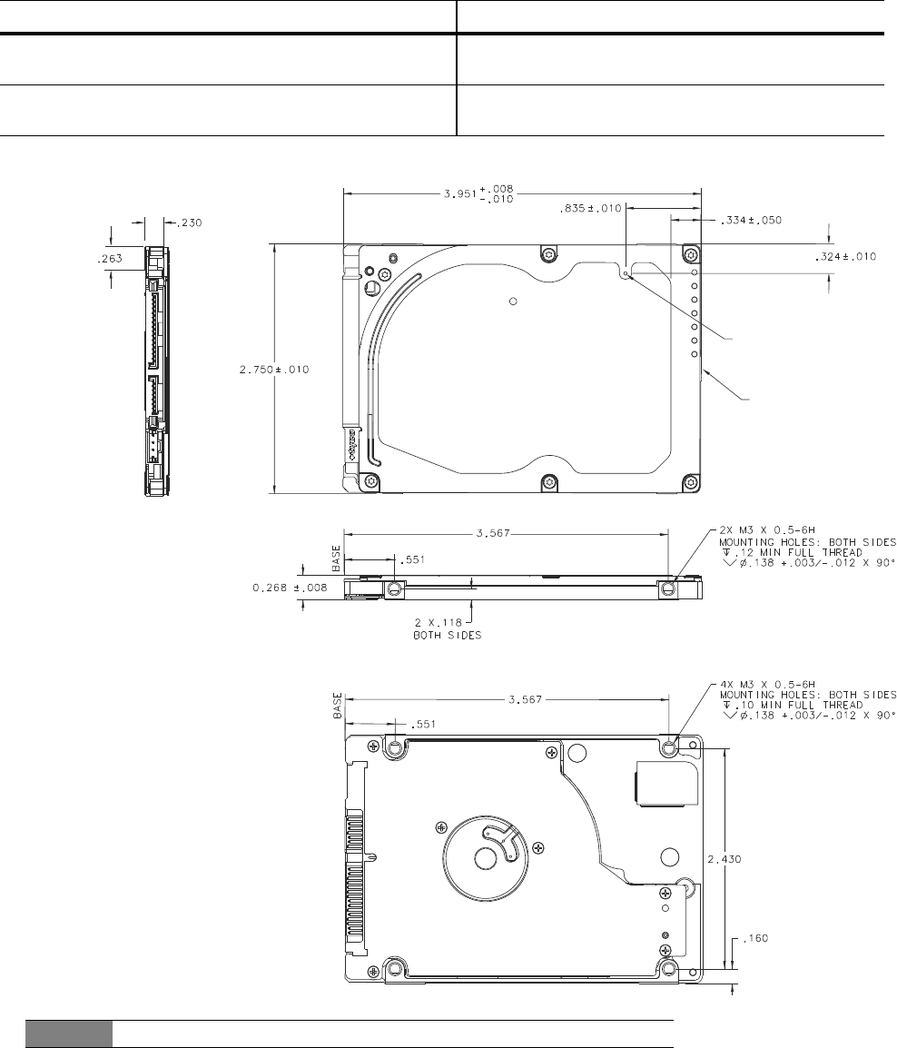
3.3 DRIVE MOUNTING
You can mount the drive in any orientation using four screws in the side-mounting holes or four screws in the bottom-
mounting holes. Refer to Figure 3 for drive mounting dimensions. Follow these important mounting precautions when
mounting the drive:
Allow a minimum clearance of 0.030 in (0.76 mm) around the entire perimeter of the drive for cooling.
Use only M3 x 0.5 mounting screws.
Do not overtighten the mounting screws. Maximum torque: 4.0 in-lb (0.4519 N-m).
Four (4) threads (0.080 in, 2.032 mm) minimum screw engagement recommended.
Avoid excessive drive distortion when mounting. Refer to the following specifications for stiffness/deflection information:
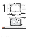
Figure 3 Mounting Dimensions (for standard models)
Top cover stiffness/deflection
Operating: no performance degradation, emitted noise,
mechanical damage, or hard errors
10 mm probe: 1.02kgf or
5 mm probe: 0.92kgf
Non-operating: no hard errors 20 mm probe: 2.0kgf at any point of top cover
20 mm probe: 15.0kgf at top cover edges only
NOTE
For reference only. May not represent actual drive.
BREATHER HOLE,
DO NOT COVER OR SEAL
RECOMMENDED CASE TEMP
MEASUREMENT LOCATION
ON THE END OF THE DRIVE