


SEAGATE VIDEO 2.5 HDD PRODUCT MANUAL, REV. A 17
4.0 SERIAL ATA (SATA) INTERFACE
These drives use the industry-standard Serial ATA interface that supports FIS data transfers. It supports ATA programmed input/output
(PIO) modes 0–4; multiword DMA modes 0–2, and Ultra DMA modes 0–6. The drive also supports the use of the IORDY signal to provide
reliable high-speed data transfers.
For detailed information about the Serial ATA interface, refer to the Serial ATA: High Speed Serialized AT Attachment specification.
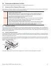
4.1 HOT-PLUG COMPATIBILITY
Seagate Video 2.5 HDD drives incorporate connectors which enable you to hot plug these drives in accordance with the Serial ATA: High
Speed Serialized AT Attachment specification revision 2.0. This specification can be downloaded from
www.serialata.org. This device
requires a COMRESET from the host after a hotplug event.
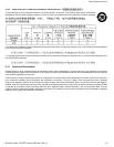
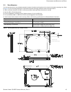
4.2 SERIAL ATA DEVICE PLUG CONNECTOR PIN DEFINITIONS
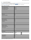
Table 8 summarizes the signals on the Serial ATA interface and power connectors. Refer to the Notes below.
NOTES
1 All pins are in a single row, with a 1.27 mm (0.050 in) pitch.
2 The comments on the mating sequence apply to the case of backplane blindmate connector only. In this case, the mating sequences
are:
• the ground pins P4 and P12.
• the pre-charge power pins and the other ground pins.
• the signal pins and the rest of the power pins.
3 There are three power pins for each voltage. One pin from each voltage is used for pre-charge when installed in a blind-mate
backplane configuration.
4 All used voltage pins (V
x
) must be terminated.
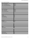
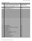
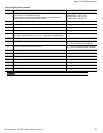
Table 8 Serial ATA Connector Pin Definitions
Segment Pin Function Definition
Signal
S1 Ground 2nd mate
S2 A+
Differential signal pair A from Phy
S3 A-
S4 Ground 2nd mate
S5 B-
Differential signal pair B from Phy
S6 B+
S7 Ground 2nd mate
Key and spacing separate signal and power segments
Power
P1 V33 3.3V power
P2 V33 3.3V power
P3 V33 3.3V power, pre-charge, 2nd mate
P4 Ground 1st mate
P5 Ground 2nd mate
P6 Ground 2nd mate
P7 V5 5V power, pre-charge, 2nd mate
P8 V5 5V power
P9 V5 5V power
P10 Ground 2nd mate
P11 Ground or LED signal If grounded, drive does not use deferred spin
P12 Ground 1st mate
P13 V12 12V power, pre-charge, 2nd mate
P14 V12 12V power
P15 V12 12V power