


12 ST1.3 Series Product Manual, Rev. C
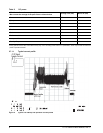
2.8.5 Shock
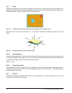
All shock measurements in this section are carried out at drive level. For all linear shock test, operating or non-
operating, the input shock level shall be measured at the frame of the disk drive at the specific location indi-
cated by the ellipse in Figure 5 below for the ZIF interface drives.
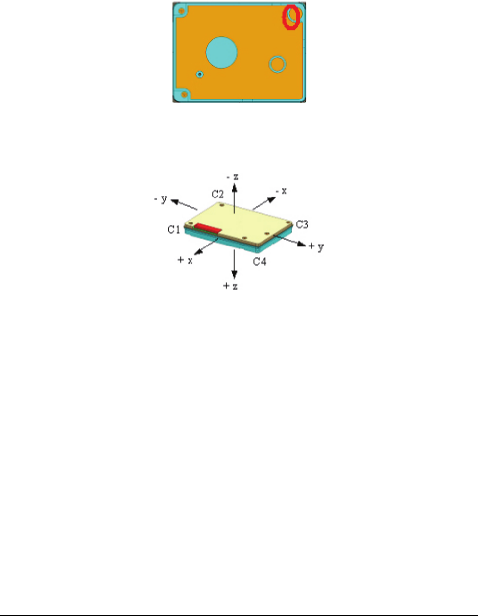
Figure 5. Location where tri-axial accelerometer will be placed on ST1.3 Series drives
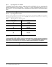
All shock test will cover all the 6 directions, +/- x, y and z axes. The drive axis definition in shown in Figure 6
below.
Figure 6. Drive axis definition for ST1.3 Series drives
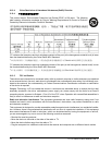
2.8.5.1 Operating shock
The drive will be subjected to 10 shocks for each direction. During the shocks, there must be a minimum delay
of 3 seconds between shock pulses. Soft errors and automatic retries are allowed during the test. No data loss
or permanent damage occurs during a half sine shock pulse of:
300 Gs, 1 msec
2.8.5.2 Nonoperating shock
The nonoperating shock level that the drive can experience without incurring any physical damage when sub-
sequently put into operation is 2000 Gs. The same applies for shock levels of 2000 Gs, 1 msec pulse duration
on fresh drives for each level.
2.8.6 Vibration
All vibration specifications assume that the drive is mounted securely in a fixture that does not have fixture
resonances in the frequency test range.