


Lyrion Series IDE Product Manual, Rev. B iii
List of Figures
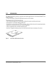
Figure 1. Lyrion Series (IDE interface) disc drive . . . . . . . . . . . . . . . . . . . . . . . . . . . . . . . . . . . . . . . . . . 1
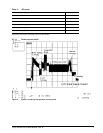
Figure 2. Typical 3.3V startup and operation current profile . . . . . . . . . . . . . . . . . . . . . . . . . . . . . . . . . . 7
Figure 3. Location where tri-axial accelerometer will be placed on Lyrion Series drives. . . . . . . . . . . . 11
Figure 4. Drive axis definition for Lyrion Series drives. . . . . . . . . . . . . . . . . . . . . . . . . . . . . . . . . . . . . . 11
Figure 5. Lyrion Series breather hole location . . . . . . . . . . . . . . . . . . . . . . . . . . . . . . . . . . . . . . . . . . . . 19
Figure 6. Lyrion Series proper handling example . . . . . . . . . . . . . . . . . . . . . . . . . . . . . . . . . . . . . . . . . 19
Figure 7. Lyrion Series mechanical dimensions—top, side and end view . . . . . . . . . . . . . . . . . . . . . . . 21
Figure 8. Lyrion Series Area for Protective Mounting . . . . . . . . . . . . . . . . . . . . . . . . . . . . . . . . . . . . . . 22