


58 Savvio 10K.4 FC Product Manual, Rev. A
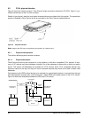
9.5 FC-AL physical interface
Figure 9 shows the location of the J1 Fibre Channel single connection attachment (FC-SCA). Figure 11 pro-
vides the dimensions of the FC-SCA connector.
Details of the physical, electrical, and logical characteristics are provided within this section. The operational
aspects of Seagate’s Fibre Channel drives are provided in the Fibre Channel Interface Manual..
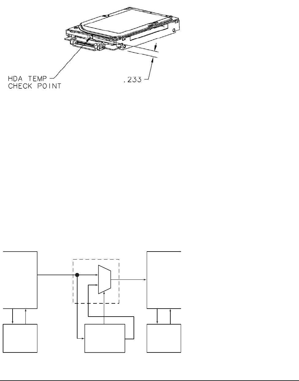
Figure 9. Physical interface
Note. Image of the HDA may not represent actual product, for reference only.
9.5.1 Physical characteristics
This section defines physical interface connector.
9.5.1.1 Physical description
FIbre Channel drives may be connected in a loop together or with other compatible FC-AL devices. A maxi-
mum of 127 devices may have addresses; however, one of the addresses is reserved for a fabric port switch
device. This means 126 addresses are available for FC-AL devices. More FC-AL compatible devices may
physically reside on the loop, but they will not be functional because they would not be able to obtain valid
addresses.
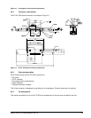
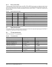
Port bypass circuits (PBCs) allow devices to be inserted into unpopulated locations or removed from the loop
with loop operation recovery after a brief interruption. These PBCs are located external to the FC-AL device.
Figure 10 shows the relationship between the PBC and FC-AL device.
Port Bypass
Circuit N–1
Select
Drive N–1
Port Bypass
Circuit N+1
Drive N+1
Drive N
Serial
In
Serial
Out
From Previous
Drive
Port Bypass
Circuit
To Next
Drive
MUX