Momentus 5400.3 SATA Blade Server Product Manual, Rev. E
9
2.9.2 Deferred spinup
Momentus 5400.3 SATA drives provide a deferred spinup feature which storage subsystem controllers can use
to sequence disc drive initialization. This is beneficial to systems which include multiple Serial ATA hard disc
drives because it allows subsystem controllers to stagger the spinup of each drive to accommodate available
power supply current. This feature does not impact time-to-ready in typical desktop systems.
To accommodate the deferred spinup of multiple disc drives in an enclosure, Momentus 5400.3 SATA disc
drives will spin up only after power is applied to the drive and after successful PHY (Physical layer) initializa-
tion. PHY initialization occurs after the PHY enters the DP7:DR_Ready state. This state is reached after a suc-
cessful exchange of Out-Of-Band (OOB) signals with a functional host-side Serial ATA port. In desktop
systems, SATA transceivers should initialize OOB as soon as power comes ready to guarantee the drive spins
up quickly. Seagate disc drives will not spin up without an operational host-side Serial ATA transceiver.
Additional details
Upon system power up, PHY communication is initiated with a COMRESET signal, which is generated by the
host-side transceiver. COMRESET is followed by a COMINIT signal generated by the disc drive transceiver.
COMRESET and COMINIT are followed by an exchange of COMWAKE signals and Align primitives. The disc
drive will spin up after the successful exchange of Align primitives cause the PHY to come ready.
For more details, refer to:
• Section 6.8 of the Serial ATA 1.0 High-Speed Serialized AT Attachment specification
• Section 6.2 of the Serial ATA II: Extensions to Serial ATA 1.0 specification
• SATA 1.0 design guides
Note. These specifications and guides are available on the Serial ATA web site (www.serialata.org).
2.9.3 Conducted noise
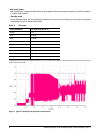
Input noise ripple is measured at the host system power supply across an equivalent 15-ohm resistive load on
the +5 volt line.
Using 5-volt power, the drive is expected to operate with a maximum of 100 mV peak-to-peak square-wave
injected noise at up to 10 MHz.
Note. Equivalent resistance is calculated by dividing the nominal voltage by the typical RMS read/write
current.
2.9.4 Voltage tolerance
Voltage tolerance (including noise):
5V ± 5%


