


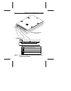
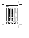

Setting master/slave jumpers
Two drives may be controlled through a single drive controller
cable with two connectors. In this case, one drive is designated
as the master and the other is designated as the slave. As shown
in Figure 1 on page 4, the jumpers on each drive must be set to
identify which drive is master and which is slave.
Connecting cables
The ST9235 Family drives use a 44-pin AT interface connector
cable with two rows of 22 female contacts on 0.079 inch (2 mm)
centers (see Figure 1). Pin assignments for the AT interface are
listed in Appendix A.
Most cables have a stripe down one side, which designates pin
1. Make sure pin 1 on the interface cable connector is aligned to
pin 1 on the drive interface connector and pin 1 on the host
connector. To assist in cable alignment, pin 20 has been removed
on the male interface connector on the drive. This type of
connector is designed to be used with a keyed cable connector
having a plug in place of pin 20.
Before mounting the drive, be sure that the connecting cable is
long enough to reach the drive, but not so long that it will be
pinched when the system enclosure is replaced. Connecting
cables for the ST9235 family drives must not be longer than 18
inches (457 mm).
Power connections
Power for the ST9235 family drives is supplied through the 44-pin
interface connector (see Appendix A for specific pin assign-
ments).
Caution. These drives can accept only +5 volts DC power. Do
not use +12 volts DC power.
ST9235 Family Installation Guide, Rev. B 3