


66
Savvio SAS Product Manual, Rev. D
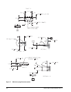
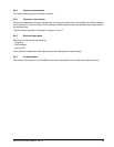
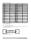
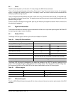
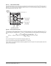
9.5.2.3 Receiver signal characteristics
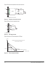
Table 28 defines the compliance point requirements of the signal at the receiver end of a TxRx connection as
measured into the test loads specified in figure 22 and figure 23.
9.5.2.3.1 Jitter
Table 29 defines the maximum allowable jitter.
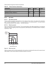
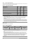
Table 28: Receiver signal characteristics
Signal characteristic Units 1.5 Gbps 3.0 Gbps
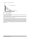
Jitter (see figure 19)
b
N/A See table 29 See table 29
2 x Z2 mV(P-P) 1,200 1,600
2 x Z1 mV(P-P) 325 275
X1
a
UI 0.275 0.275
X2 UI 0.50 0.50
Skew
d
ps 80 75
Max voltage (non-op) mV(P-P) 2.000 2.000
Minimum OOB ALIGN burst amplitude
c
mV(P-P) 240 240
Maximum noise during OOB idle time
c
mV(P-P) 120 120
Max near-end crosstalk
e
mV(P-P) 100 100
a The value for X1 shall be half the value given for total jitter in table 29. The test or analysis shall include the effects of
a single pole high-pass frequency-weighting function that progressively attenuates jitter at 20 dB/decade below a
frequency of ((bit rate) / 1,667).
b The value for X1 applies at a total jitter probability of 10
-12
. At this level of probability direct visual comparison
between the mask and actual signals is not a valid method for determining compliance with the jitter output
requirements.
c With a measurement bandwidth of 1.5 times the baud rate (i.e. 4.5 GHz for 3.0 Gbps).
d The skew measurement shall be made at the midpoint of the transition with a repeating 0101b pattern on the physical
link. The same stable trigger, coherent to the data stream, shall be used for both the Rx+ and Rx- signals. Skew is
defined as the time difference between the means of the midpoint crossing times of the Rx+ signal and the Rx- signal.
e Near-end crosstalk is the unwanted signal amplitude at receiver terminals DR, CR, and XR coupled from signals and
noise sources other than the desired signal. Refer to SFF-8410.
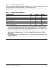
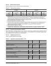
Table 29: Maximum allowable jitter
1.5 Gbps
m,
n
3.0 Gbps
m,
n
Deterministic jitter
q
Total jitterc
,
d
,
e
,
f Deterministic jittere Total jitterc
,
d
,
e
,
f
0.35 0.55 0.35 0.55
a Units are in UI.
b The values for jitter in this section are measured at the average amplitude point.
c Total jitter is the sum of deterministic jitter and random jitter. If the actual deterministic jitter is less than the maximum
specified, then the random jitter may increase as long as the total jitter does not exceed the specified maximum total
jitter.
d Total jitter is specified at a probability of 10
-12
.
e The deterministic and total values in this table apply to jitter after application of a single pole high-pass frequency-
weighting function that progressively attenuates jitter at 20 dB/decade below a frequency of ((bit rate) / 1
667).
f If total jitter received at any point is less than the maximum allowed, then the jitter distribution of the signals is allowed
to be asymmetric. The total jitter plus the magnitude of the asymmetry shall not exceed the allowed maximum total
jitter. The numerical difference between the average of the peaks with a BER < 10
-12
and the average of the
individual events is the measure of the asymmetry. Jitter peak-to-peak measured < (maximum total jitter -
|Asymmetry|).