


Savvio 15K.1 FC Product Manual, Rev. B
v
List of Figures
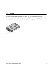
Figure 1. Savvio 15K.1 family disc drive . . . . . . . . . . . . . . . . . . . . . . . . . . . . . . . . . . . . . . . . . . . . . . . . . 1
Figure 2. Typical ST973451FC drive +12V and +5V current profiles . . . . . . . . . . . . . . . . . . . . . . . . . . 25
Figure 3. Typical ST936751FC drive +12V and +5V current profiles . . . . . . . . . . . . . . . . . . . . . . . . . . 26
Figure 4. ST973451FC DC current and power vs. input/output operations per second at 1 Gbit . . . . . 27
Figure 5. ST973451FC DC current and power vs. input/output operations per second at 2 Gbit . . . . . 27
Figure 6. ST973451FC DC current and power vs. input/output operations per second at 4 Gbit . . . . . 28
Figure 7. ST936751FC DC current and power vs. input/output operations per second at 1 Gbit . . . . . 29
Figure 8. ST936751FC DC current and power vs. input/output operations per second at 2 Gbit . . . . . 29
Figure 9. ST936751FC DC current and power vs. input/output operations per second at 4 Gbit . . . . . 30
Figure 10. Locations of the HDA temperature check point . . . . . . . . . . . . . . . . . . . . . . . . . . . . . . . . . . . 31
Figure 11. Recommended mounting . . . . . . . . . . . . . . . . . . . . . . . . . . . . . . . . . . . . . . . . . . . . . . . . . . . . 33
Figure 12. Drive dimensions (inches) . . . . . . . . . . . . . . . . . . . . . . . . . . . . . . . . . . . . . . . . . . . . . . . . . . . 36
Figure 13. Air flow . . . . . . . . . . . . . . . . . . . . . . . . . . . . . . . . . . . . . . . . . . . . . . . . . . . . . . . . . . . . . . . . . . 42
Figure 14. Physical interface . . . . . . . . . . . . . . . . . . . . . . . . . . . . . . . . . . . . . . . . . . . . . . . . . . . . . . . . . . 57
Figure 15. Port bypass circuit physical interconnect . . . . . . . . . . . . . . . . . . . . . . . . . . . . . . . . . . . . . . . . 57
Figure 16. FC-AL SCA device connector dimensions . . . . . . . . . . . . . . . . . . . . . . . . . . . . . . . . . . . . . . . 58
Figure 17. FC-AL transmitters and receivers . . . . . . . . . . . . . . . . . . . . . . . . . . . . . . . . . . . . . . . . . . . . . . 60
Figure 18. Transmit eye diagram . . . . . . . . . . . . . . . . . . . . . . . . . . . . . . . . . . . . . . . . . . . . . . . . . . . . . . . 65
Figure 19. Receive eye diagram . . . . . . . . . . . . . . . . . . . . . . . . . . . . . . . . . . . . . . . . . . . . . . . . . . . . . . . 65