


LD25 Series 5400.2 Product Manual, Rev. C
23
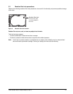
Each cable is keyed to ensure correct orientation.
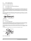
3.4.2 How to configure Parallel ATA (PATA) drives
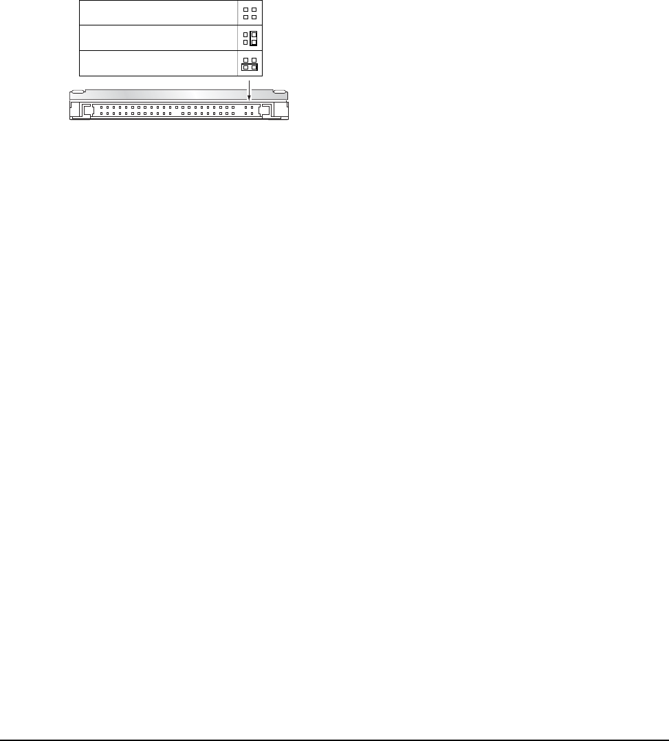
Use the options jumper block shown in Figure 6 to configure the drive for operation. This jumper block is the
4-pin header adjacent to pins 1 and 2 of the I/O signal pins. For additional information about using the Cable
select option, see Section 3.4.2.1.1.
3.4.2.1 How to configure the drive as a master or slave
Refer to Figure 6 to set the master, slave, or cable select option. The “Master or single drive” option is the fac-
tory default setting.
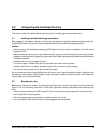
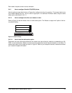
Figure 6. Jumper settings
3.4.2.1.1 How to use the cable-select option
Computers that use cable select determine the master and slave drives by selecting or deselecting pin 28,
CSEL, on the interface bus. Master and slave drives are determined by their physical position on the cable. To
enable cable select, set a jumper as shown in Figure 6. Refer to your computer manual to determine whether
your computer supports this option.
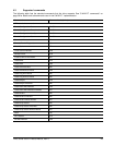
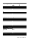
Drive is slave
Drive is master (or single drive)
Cable select