


41
Appendix A: Connections
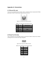
A.1 Ethernet Pin outs
The LS100 uses standard Ethernet connector, which is a shielded connector compliant with AT&T258
specifications. Table A-1 shows the pin assignment and the wire color.
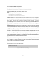
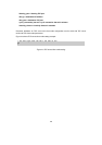
Figure A-1 Pin layout of the RJ45 connector
Table A-1. Pin assignment of the RJ45 connector
Pin Description Color
1 Tx+ White with orange
2 Tx- Orange
3 Rx+ White with green
4 NC Blue
5 NC White with blue
6 Rx- Green
7 NC White with brown
8 NC Brown
A.2 Serial Port Pin Outs
The pin assignment of the LS100 DB9 connector is summarized in Table A-2. Each pin has a function
according to the serial communication type configuration.
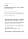
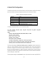
6 7 8 9
1 2 3 4 5
Figure A-2 Pin layout of the DB-9 connector
Table A-2. Pin assignment of the DB-9 connector
Pin RS232
1 -
2 Rx
3 Tx
4 DTR
5 GND
6 DSR
7 RTS
8 CTS
9 -