


ENGLISH
– 6 –
SYSTEM DESCRIPTION
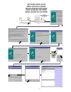
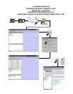
The Shure UA888/UA111 System lets you use a computer to monitor and control up to 64 Shure UHF Wireless receivers. It is de-
signed for installed sound reinforcement applications, including theaters, larger houses of worship; touring sound systems; and au-
dio/video rental applications.
System Components
S UA888 or UA111 Interface Module
S Windows-based Shure Wireless Workbencht software
S Connecting cables
S An IBM compatible PC (not supplied)
S Shure U4S or U4D diversity UHF receivers. (Shure U4
receivers are supplied separately).
System Features
S Monitors and controls* up to 32 receivers (64 channels
maximum)
S RF level monitor
S Diversity signal monitor
S Audio level monitor
S Transmitter battery level monitor function
S Name/label monitor and control
S Frequency monitor and control
S Frequency group/channel monitor and control functions
(TV channels in U.S. models)
S Squelch monitor and control
S Receiver lock/unlock
S RF level history function that identifies ”dead” spots in
the performing area
S Frequency scanner function that identifies local RF activity
S RS–232 serial interface
S Shure Linkt interfaces to other Shure devices
(UA888 only)
S Scene creation and storage capability
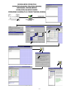
*NOTE: The “Monitor” feature lets you view various wireless system parameters and observe RF and audio performance, in real time, on the computer monitor. The “Control”
feature lets you actually change receiver parameters from your computer terminal.
Trademark Notification: Shure
is a registered trademark of Shure Incorporated. Shure Linkt and Shure Wireless Workbencht are trademarks of Shure Incorporated. IBM
is a registered trademark of International Business Machines Corporation. Microsoft
is a registered trademark of Microsoft Corporation.
Minimum Computer Requirements
S 300 MHz IBM-compatible computer
S 32 MB RAM
S 20 MB hard drive
S Windows 98 or later (including Windows 2000 and
Windows XP)
S One available RS–232 serial COM port
S One RS–232 cable
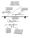
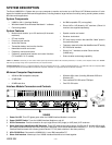
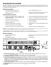
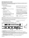
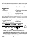
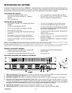
Interface Module Connectors and Controls
1 2
LINK
5 6
5
3
UA888
1. Power On LED. This LED glows green when the UA888 Interface Module is turned on.
2. Power ON/OFF Switch. Turns the UA888 Interface Module on and off.
3. 25-Pin Connectors. Provide connection for up to eight Shure U4S (single) or U4D (dual) UHF receivers.
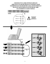
4. Shure Link Device Identification DIP Switches. These DIP switches are used to set the Link Device I.D. Number. When multi-
ple UA888 Interface Modules are linked, each one is assigned a Link Device Identification Number (0, 1, 2, or 3). Each UA888
Interface Module comes with a factory preset Device I.D. of 0 (both switches in the down position).
5. 9-Pin RS-232 Port. Connects the UA888/UA111 to an IBM–compatible PC.
6. Shure Link Interface. Allows up to four UA888 Interface Modules to be linked together.