Chapter 4 Troubleshooting & Repair Series 24-HP Instruction Manual
4-8 IM-24-HP
Symptom: Meter Displays Temperature Fault
1. For remote mounted electronics, carefully check all the wiring
connections in the remote mount junction box. There are 18
connections that must be correct, verify each color (black and
red), shield, and wire number.
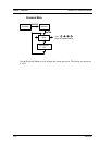
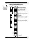
2. Go to the first column of the hidden diagnostics and check the
resistance of the rtd1. It should be about 1080 ohms at room
temperature.
3. Using ESD precautions and hazardous area precautions, re-
move the electronics enclosure window cover. Disconnect the
temperature sensor (on the right) from the pressure / tempera-
ture board (the pressure / temperature board is the second board
below the microprocessor (display) board. Measure the resis-
tance across the outside pins of the temperature sensor connec-
tor. It should read approximately 1080 ohms at room tempera-
ture (higher resistance at higher temperatures). With the tem-
perature sensor still disconnected, measure the current across
the two outside pins of the exposed connector on the tempera-
ture / pressure board. The current should be approximately
.0002 amps. Now reconnect the temperature sensor and meas-
ure the voltage across the two inside pins (insert probes into the
connector where the wires enter it). This value should be ap-
proximately .2 volts (or .0002 amps times measured resistance,
.216 volts at room temperature).
4. Consult factory with findings
Symptom: Meter Displays Pressure Fault
1. For remote mounted electronics, carefully check all the wiring
connections in the remote mount junction box. There are 18
connections that must be correct, verify each color (black and
red), shield, and wire number.
2. Using ESD precautions and hazardous area precautions, re-
move the electronics enclosure window cover. Disconnect the
pressure sensor (on the left) from the pressure / temperature
board (the pressure / temperature board is the second board be-
low the microprocessor (display) board. Measure the resistance
across the outside pins of the pressure sensor connector, then
across the inside pins. Both readings should be approximately
4000 ohms. With the pressure sensor still disconnected, meas-
ure the current across the two outside pins of the exposed con-


