


Configuring the MP Modem to Report GPS and I/O
Data
Rev 1.4 Draft Mar.08 61
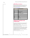
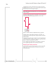
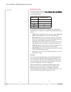
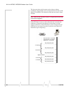
Typicallyananaloginputdeviceshouldbeconnectedbetween
Ground(pin10)andtheinputport(Pin7,8,14,or15).
Figure 7-4: A sensor wired to Pin 7 (analog input) and Pin 10 (Ground).
Theanaloginputportsusea10‐bit(1024‐step)analog‐to‐
digitalconverteroverarangefrom0to3.45
VDC,yieldinga
digitalstepresolutionof0.0032
V.
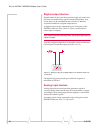
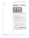
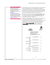
Example: analog sensor connections
AnI/Ocableforananalogsensorrequiresawiretooneofthe
analoginputpins(suchas#7)andonewiretotheGroundpin
(#10).
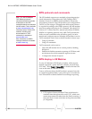
I/O configuration using AT or 3G Watcher
commands
Onceasensor,gauge,button,orswitchisphysicallyconnected
totheMPmodem,theMPmodemmustbeconfiguredto
managetheinputfrom,oroutputto,thedevice.Thisconfigu
‐
rationcanbedoneusingeitherATcommandsorusing3G
Watcher.
ForalistofATcommands,pleaseseetheMP3GModemsAT
CommandReferencemanual(document#2130810).
Thereareseparatewindowsin3GWatcherforconfiguringthe
analoganddigitalports.
~