


6. TROUBLESHOOTING page 17
Model AM-255
6.1.3. Battery Charger:
The Battery Charger is wired directly into Molex connector to the AM-255 board. To disconnect,
the Molex pins must be removed from the housing by inserting a small screwdriver or sharp
pointed object into the slots in the housing and pressing down, while pulling gently on the wire.
The ac input plugs into the charger with a standard IEC connector. To reinstall the battery
charger insert the pins into the Molex housing, and reconnect the ac input to the IEC connector.
6.1.4. Lamps:
The Lamps are soldered to the circuit board.
6.2. TROUBLESHOOTING GUIDE
NOTE:
Some steps will require tools, supplies, DMM, and possibly an oscilloscope. These steps
should only be performed by qualified service personnel.
Perform a physical inspection of the unit, looking for faulty or broken wiring, foreign material,
broken or damaged components, and loose connections. Proceed by checking the individual
assemblies as follows:
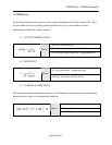
6.2.1. Battery and Charger:
If the unit is not operating at all and the green power LED is off, use the following steps to
check the battery and charger. Refer to Drawing 3. "Controller Board" (Appendix F.)
Open the front panel and disconnect the positive lead to the battery. Measure the voltage across
the battery with a meter; it should be at least 12.4 volts. If the voltage is low or not present then
the battery must be charged or replaced.
NOTE:
Do not go to step 2 until the battery voltage is 12.4 or greater.