


2
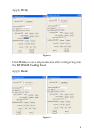
Layout
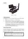
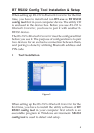
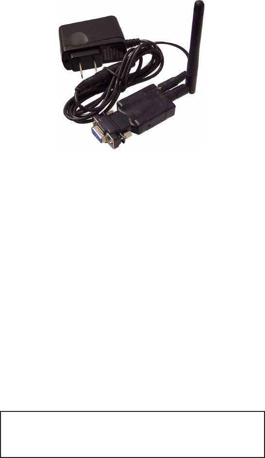
Figure 1: Layout
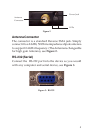
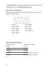
LED Indicators
See Figure 2 on the next page for the location of the LEDs.
• Red: Power indicator - on all the time.
• Green: Before connecting to synchronize between
the serial device and the BT RS232 Config Tool
software, the green LED will be blinking.After
connecting to synchronize between the device and
the BT RS232 Config Tool software, the green &
red LED will blinked alternately.
DC-In Power Jack
Connect the power adapter to the power jack then plug
the power adapter into a reliable power outlet. When
power is properly supplied, the red LED will be on, see
Figure 2 on the next page.
Note: If the serial port can provide 5V DC, 150mA
on pin #9 of its DB9 connector, then the power
adapter is not needed.