


CP2112-EK
Rev. 0.2 7
5.2. Universal Serial Bus (USB) Interface (P1)
A Universal Serial Bus (USB) connector (P1) is provided to facilitate connections to the USB interface on the
CP2112. See Table 2 for the USB pin definitions.
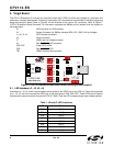
5.3. SMBus Signals (TB1, H1)
The SMBus interface terminal block and access headers are included to easily interace SMBus devices to the
evaluation board. The terminal block can be used to connect wires to the board, and the access connectors can be
used to connect scope probes to the SMBus interface for debugging. The signals that are accessible through these
two connectors are SDA, SCL, GND, and the external pull-up voltage signal.
5.4. VDD and VIO Power Connector (J6)
This header (J6) is included on the evaluation board to provide several power options. The following describes the
function of each pin:
Pins 1–2: Connect CP2112 VIO input (pin 5) to CP2112 VDD (Pin 6). Remove the shorting block to power VIO
from an external source.
Pins 3–4: Connects the main +3 V net to the CP2112 VDD (Pin 6). The main +3 V net powers the other
components (eight green LEDs) on the board.
5.5. SMBus Pull-Up Voltage Connector (J7)
This header (J7) is included on the evaluation board to provide power options for SMBus pull-up voltage. The
following describes the function of each pin:
J7[1:2]: Connects CP2112 VIO pin (Pin 5) to the 4.7 k pull-up resistors located on the evaluation board.
J7[2:3]: Connects the External Pull-Up signal from TB1 (Pin 4) to the 4.7 kpull-up resistors on the evaluation
board.
5.6. SUSPEND LED Connector (J8)
The J8 header is used to connect the CP2112 SUSPEND pin (Pin 17) to the DS8 red LED. When the LED is on,
the device has enumerated with the PC operating normally. When the LED is off, the device has not yet
enumerated or is in the USB Suspend state.
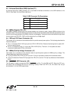
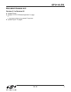
Table 2. USB Connector Pin Descriptions
Pin # Description
1 VBUS
2D-
3D+
4 GND (Ground)