


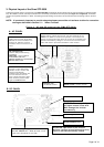
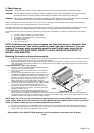
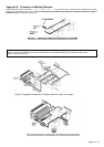


3. Physical Layout of the Sima STP-3000
Power flows logically from the rear terminals of the
Sima STP-3000
unit forward to the front panel of the AC output receptacle (or optional junction
box). All indicators, controls, and output connections are conveniently accessed from the front panel (See
Figure 3a
and
Figure 3b
). Their detail
functions are explained in Section 6.1 below. A circulating fan draws cooling-air in from the rear and forces the flow out through vents on the front
panel.
NOTE: It is extremely important to provide adequate airspace around the unit surfaces to allow for convection
cooling as described in Section 5.1 –
Where To Install.
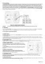
Figure 3. AC and DC panels of the SIMA STP-3000
A. AC PANEL
AC GFI outlet (Inverter output)
OVER TEMP INDICATOR:
Inverter is shut down while
indicator is ON. Inverter will
restart automatically.
Indicator lamp and alarm will
turn off when the inverter
cools. Lights and alarm alerts
when inverter protects itself
against OVERHEATING.
ON/OFF SWITCH:
Leave in OFF position during
installation
CAUTION! THIS IS NOT A
DISCONNECT SWITCH.
REMOVE POWER AT THE SOURCE
BEFORE SERVICING.
BAR GRAPH METERS:
Display battery voltage and current. Current should be in the
GREEN zone ONLY for continuous operation; The inverter will
operate for several minutes when the current in the Yellow zone:
operation with battery voltage or current in the red zone of the
meter will result in protective shutdown of the inverter.
OVERLOAD INDICATOR:
Lights when inverter shuts down
because of severe overload. Turn
inverter off. Remove cause of
overload, and turn inverter on to
reset .
Modular jack
for Remote control
B. DC PANEL
CAUTION: Reverse polarity
will open internal fuses and
MAY damage the inverter
p
ermanentl
y
BLACK: Negative “-”
RED: Positive “+”
WARNING: Operation of the inverter
without a proper ground connection may
result in an electrical safety hazard
Ventilation Opening
DO NOT OBSTRUCT – Allow at least 4 inch
(100 mm) clearance for air flow.
CHASSIS GROUND LUG.
Page 4 of 14