


Initial Hitch &
Tube Installation
11
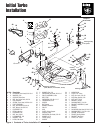
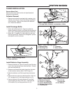
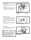
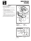
Figure 1. Install Hitch Plate
A. Hitch Plate E. Upper & Lower
B. Heat Shield Bumper
C. Capscrews, F. Washer
1/2-13 x 1-1/4 G. New Holes, 17/32”
D. Locknuts, 1/2-13 H. Existing RH Holes
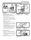
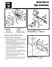
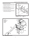
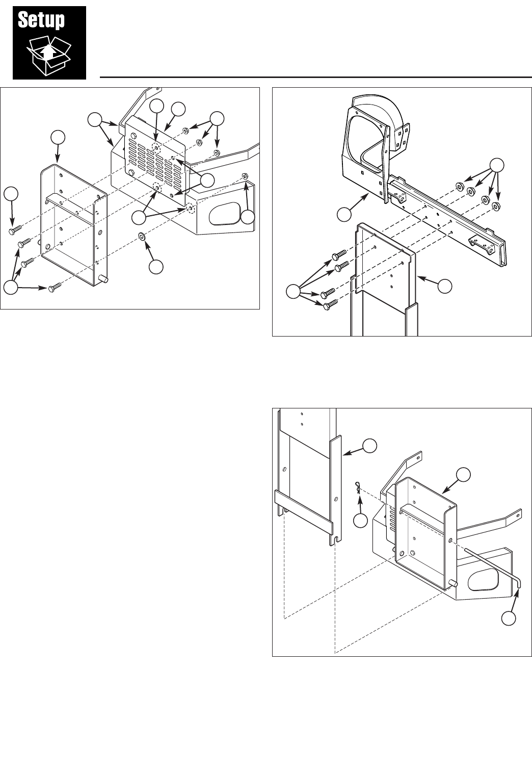
Figure 3. Install Back Plate
A. Back Plate and Support C. Hitch Plate
B. Hair Pin D. Rod
B
A
D
C
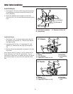
Figure 2. Install Hitch Assembly
A. Horizontal Support C. Nut, 3/8-16
B. Capscrew, 3/8-16 x 3/4 D. Back Plate
C
B
A
D
D
C
HITCH & TUBE INSTALLATION
Install Hitch Plate and Back Plate
1. Remove and discard right side hardware holding heat
shield (B, Figure 1) to upper and lower bumper (E) to
existing right hand holes (H).
2. Enlarge upper existing hole (H) to 17/32”. Install
hitch plate (A) to upper and lower bumper (E) and
heat shield (B) using upper existing hole (H) and one
1/2-13 x 1-1/4 capscrew and 1/2-13 nut.
3. Square hitch plate (A, Figure 1) to upper & lower
bumper (E) and use as a template to mark and drill
three new holes 17/32” (G)
4. Secure hitch plate (A, Figure 1) to upper & lower
bumper (E) with 1/2-13 x 1-1/4 capscrews (C) washer
(F) and 1/2-13 locknuts (D) as shown.
5. Install the horizontal support (A, Figure 2) on the
back plate (D). Secure with four 3/8-16 x 3/4 cap-
screws (B), 3/8-16 locknuts (C).
6. Set the back plate and support (A, Figure 3) onto pins
of hitch plate (C). Secure with rod (D) and hair pin
(B).
D
E
A
F
G
G
C
B
H