


D
ESCRIPTION
OF
H
ARDWARE
1-5
Status LEDs
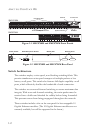
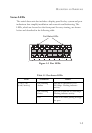
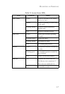
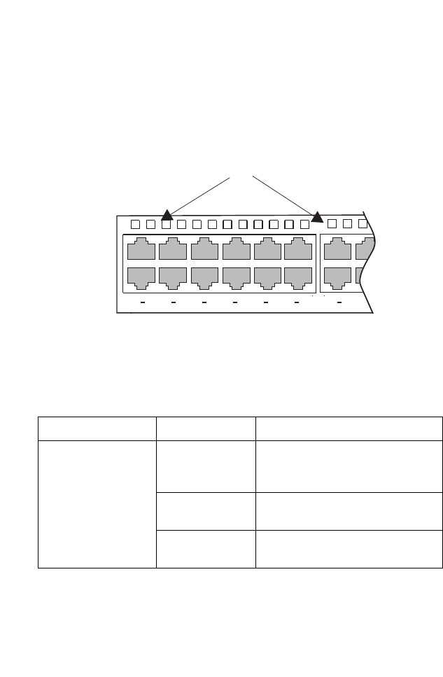
The switch base unit also includes a display panel for key system and port
indications that simplify installation and network troubleshooting. The
LEDs, which are located on the front panel for easy viewing, are shown
below and described in the following table.
Figure 1-3 Port LEDs
Table 1-1 Port Status LEDs
LED Condition Status
1~24/1~48
(Link/Activity)
On/Flashing
Amber
Port has a valid link at 10 or
100 Mbps. Flashing indicates
activity.
On/Flashing
Green
Port has a valid link at 1000 Mbps.
Flashing indicates activity.
Off There is no traffic passing through
the port.
12
3
4
5
6
7
89
10
11
12
13
14
15
16
14
13
16
15
2
1
4
3
6
5
8
7
10
9
12
11
Port Status LEDs