


2102 Alarm Panel
Page 3 2102 Alarm Panel
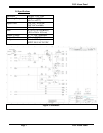
Terminal 1: Normally open: Connects to
Commons during alarm.
Terminal 2: Common.
Terminal 3: Normally connected to
Common: Opens during alarm.
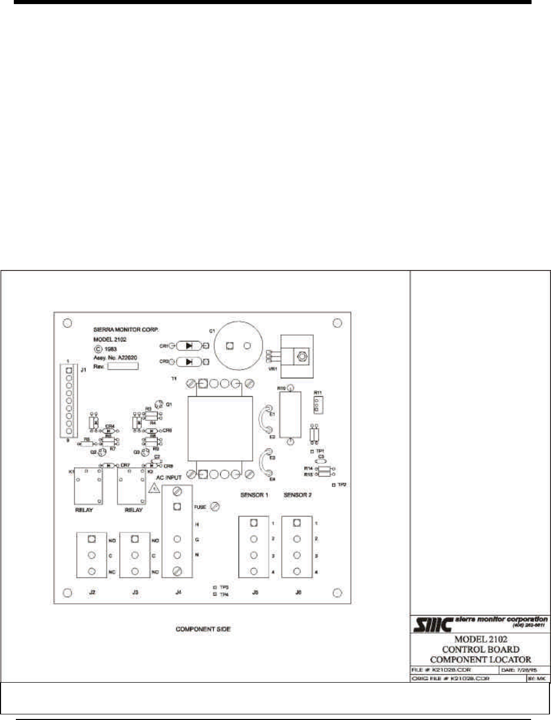
Connect the 120 VAC power source to
the large terminal strip marked “N” “G”
“H” for Neutral, Ground, Hot. Install the
protective plate which is provided with
the Model 2102 over the AC Connection
for safety.
As there is no “ON/OFF” switch on the
central panel the system will start-up as
soon as the supply AC is turned “ON”.
Be sure that all sensor and relay
connections are completed prior to
“power on”. When power is connected
both channels will go into warm up
mode as described in the gas monitor
instruction manual. When the panel
lights change to green the warm-up is
complete and the system is in the normal
monitoring mode.
If the monitors fail to operate correctly
(see respective manual) measure the line
voltage (terminals 2 and 3 at the
monitor. If the voltage is below 9 VDC,
increase the power supply voltage by
adjusting the potentiometer (R11) on the
controller board until the monitor
receives 9 VDC minimum.
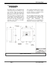
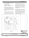
Figure 2 Component Locator