


14 15
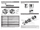
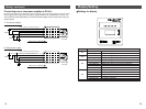
Wiring ( continued )
24VDC
24VDC
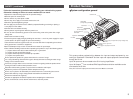
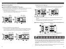
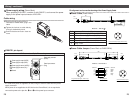
Brown : 24VDC (for solenoid valves/output)
White : 0V (for solenoid valves/output)
Grey : Earth
Blue : 24VDC (for input and control)
Black : 0V (for input and control)
Cable Part No. : EX500-AP -S
24VDC
Brown : 24VDC (for solenoid valves/output)
White : 0V (for solenoid valves/output)
Grey : Earth
Blue : 24VDC (for input and control)
Black : 0V (for input and control)
Cable Part No. : EX500-AP -S
Power supply
connector
Power supply
connector
1
34
5
2
1
34
5
2
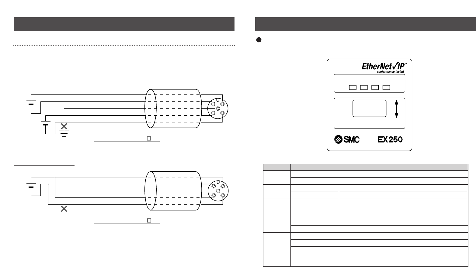
Display/Setting
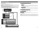
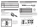
Connecting one or two power supplies to SI Unit.
Both single power supply and two power supply systems can be adopted, however, the
wiring shall be made separately (for solenoid valves/output and for input and control) for
either system.
A. Two power supplies
B. Single power supply
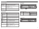
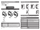
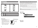
Settings for display
Display Contents
SOL
OFF The power supply for solenoids is insufficient
Green light ON The power supply for solenoids is normal
PWR
OFF The power supply for input and control is insufficient
Green light ON The power supply for input and control is normal
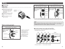
MS
OFF The power supply for control is OFF
Green light ON Operating normally
Green flashing Setting error (Device has not been configured)
Red flashing Recoverable internal error
Red light ON Unrecoverable internal error
NS
OFF The power supply for control is OFF or IP address not set
Green flashing EtherNet/IP-level communication not established
Green light ON Multiple EtherNet/IP-level communications established
Red flashing Multiple EtherNet/IP-level communications time out
Red light ON IP address duplicated