


2-30
Chapter 2: Hardware information
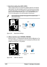
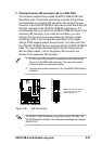
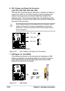
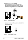
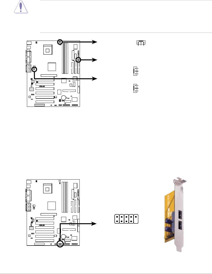
6. CPU, Chassis, and Power Fan Connectors
(3-pin CPU_FAN, PWR_FAN, CHA_FAN)
The three fan connectors support cooling fans of 350mA (4.2 Watts) or
a total of 1A (12W) at +12V. Orient the fans so that the heatsink fins
allow air flow to go across the onboard heatsink(s) instead of the
expansion slots. The fan wiring and plug may vary depending on the
fan manufacturer. Connect the fan cable to the connector matching the
black wire to the ground pin.
Figure 2-40 CPU, Chassis, and Power Fan Connectors
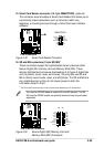
Figure 2-41 USB Header
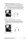
Do not forget to connect the fan cables to the fan connectors. Lack of
sufficient air flow within the system may damage the motherboard
components. These are not jumpers! DO NOT place jumper caps on
the fan connectors!
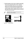
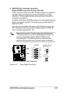
7. USB Header (10-1 pin USB23)
If the USB port connectors on the rear panel are inadequate, a USB
header is available for two additional USB port connectors. Connect a
2-port USB connector set to the USB header and mount the USB
bracket to an open slot in the chassis.
®
P4B-E
P4B-E 12-Volt Fan Connectors
PWR_FAN
CHA_FAN
GND
Rotation
+12V
CPU_FAN
GND
Rotation
+12V
GND
Rotation
+12V
®
P4B-E
P4B-E USB Header
USB23
1
5
6
10
1: USB Power
2: USBP2–
3: USBP2+
4: GND
5: NC
6: USB Power
7: USBP3–
8: USBP3+
9: GND