


xvii
F
IGURES
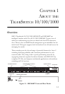
Figure 1-1. SMC8648T Front and Rear Panels . . . . . . . . . . . . . . . . . . 1-1
Figure 1-2. SMC8624T Front and Rear Panels . . . . . . . . . . . . . . . . . . 1-2
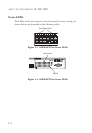
Figure 1-3. SMC8648T Port Status LEDs . . . . . . . . . . . . . . . . . . . . . 1-4
Figure 1-4. SMC8624T Port Status LEDs . . . . . . . . . . . . . . . . . . . . . 1-4
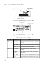
Figure 1-5. SMC8648T System Status LEDs . . . . . . . . . . . . . . . . . . . 1-6
Figure 1-6. SMC8624T System Status LEDs . . . . . . . . . . . . . . . . . . . 1-6
Figure 1-7. SMC8624T Power Supply Receptacles . . . . . . . . . . . . . . 1-7
Figure 1-8. SMC8648T Power Supply Receptacles . . . . . . . . . . . . . . 1-7
Figure 2-1. Collapsed Backbone . . . . . . . . . . . . . . . . . . . . . . . . . . . . . 2-2
Figure 2-2. Network Aggregation Plan . . . . . . . . . . . . . . . . . . . . . . . . 2-3
Figure 2-3. Remote Connection with Fiber Cable . . . . . . . . . . . . . . . 2-4
Figure 2-4. Making VLAN Connections . . . . . . . . . . . . . . . . . . . . . . . 2-5
Figure 3-1. RJ-45 Connections . . . . . . . . . . . . . . . . . . . . . . . . . . . . . . 3-2
Figure 3-2. Attaching the Brackets . . . . . . . . . . . . . . . . . . . . . . . . . . . 3-5
Figure 3-3. Installing the Switch in a Rack . . . . . . . . . . . . . . . . . . . . . 3-5
Figure 3-4. Attaching the Adhesive Feet . . . . . . . . . . . . . . . . . . . . . . . 3-6
Figure 3-5. Inserting an SFP Transceiver into a Slot . . . . . . . . . . . . . 3-7
Figure 3-6. Power Receptacle . . . . . . . . . . . . . . . . . . . . . . . . . . . . . . . 3-8
Figure 3-7. Serial Port (DB-9 DTE) Pin-Out . . . . . . . . . . . . . . . . . . . 3-9
Figure 4-1. Making Twisted-Pair Connections . . . . . . . . . . . . . . . . . . 4-2
Figure 4-2. Wiring Closet Connections . . . . . . . . . . . . . . . . . . . . . . . . 4-3
Figure 4-3. Making LC Port Connections . . . . . . . . . . . . . . . . . . . . . . 4-5
Figure B-1. RJ-45 Connector Pin Numbers . . . . . . . . . . . . . . . . . . . . B-1
Figure B-2. Straight-through Wiring . . . . . . . . . . . . . . . . . . . . . . . . . . B-3
Figure B-3. Crossover Wiring . . . . . . . . . . . . . . . . . . . . . . . . . . . . . . . . B-4