2-8
ROUTING SWITCHER SYSTEM (E)
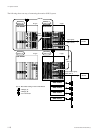
2-13. Monitor Function (BKDS-V3292B only)
(Input) 128 65
64
Input Input
1
1
Input Monitor
(Separate connection)
Output
64
DVS-V6464B
(A Type)
DVS-V6464B
(B Type)
DVS-V6464B
(D Type)
DVS-V6464B
(C Type )
65
128
(Output)
Output
Output Monitor (Separate connection)
or
Input + Output Monitor (Combined connection)
2-13. Monitor Function (BKDS-V3292B only)
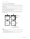
If a DVS-V3232B/V6464B is equipped with the optional BKDS-V3292B, any input/output signal can be
monitored. The input and output signals can be observed on different monitors or on the same monitor by
switching channels.
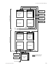
By connecting the monitor signals of several switchers in cascade form, all input and output signals can be
observed on one monitor.
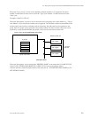
The crosspoints of monitor signals are controlled by the monitor S-BUS (the control line similar to the
standard S-BUS although it controls only the monitor system).
The primary station on the monitor S-BUS is independent from the primary station on the standard S-BUS.
Therefore, several monitor S-BUS can be set to one system.
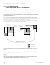
For example, switchers (P-2) and (P-3) in the figure on next page serve as the primary station on the
monitor S-BUS independently, while the switcher (P-1) serves as the primary station on the standard S-
BUS and monitor S-BUS.
m
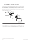
1. For DVS-V3232B/V6464B routing system, the primary station on the standard S-BUS and monitor S-
BUS should be the same.
However, for the monitor S-BUS which does not include the primary station on the standard S-BUS,
any switcher can be assigned the primary station.
2. BKS-R1601/R3203/R3206 cannot be used as a secondary station on the monitor S-BUS.


