


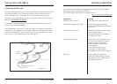
12
© 2001 - Sony Australia
13© 2001 - Sony Australia
INSTALLING THE DRIVE
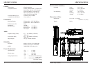
System Requirements
To ensure stable performance, the following system specications are recommended.
OS DOS 6.xx or higher, Windows 3.1x, 95/98/ME/2000/
NT 4.0, OS/2 Warp 3.0 or higher.
Interface Vacant IDE interface connector
NOTE: To operate the drive using DOS 6.xx or higher you will need to
install the DOS device drivers. These are available for free download
from our support web site:
http://www.sony.com.au/support/itp
Hardware Installation
Please refer to your PC’s user manual and follow their guidelines for adding
hardware components. Always follow their anti-static precautions.
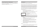
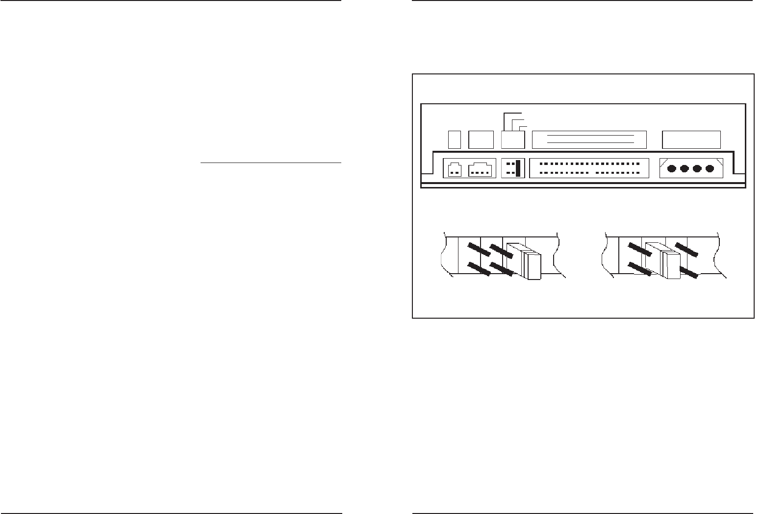
1 Set the Master/Slave jumper on CD-ROM rear panel (refer to gure 1)
2 Locate an empty drive bay and slide the CD-ROM drive into the bay. Secure
with four screws.
3 Connect the power supply cable to the CD-ROM drive. (Ensure the pin
denition of power connector is the same as shown in gure 1).
4 Connect the 40 pin IDE / ATAPI cable to the CD-ROM drive according to the
description in gure 1 (Note: Pin 1 on the cable is generally indicated by a
red stripe along the edge of the ribbon cable).
5 Connect the sound cable from the Analog Audio on the rear panel of
CD-ROM to your sound card (if you have a sound card in your system).
6 Follow you PC’s user manual to re-assemble your PC.
NOTE: For optimum performance on Windows based systems the drives DMA
setting in the device manager should be enabled. Refer to your Systems help
menu for assistance.
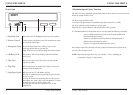
Connections and Settings
There are three pairs of jumpers, MA (Master), SL (Slave) and CS (Cable Select) on
the rear panel of your CD-ROM drive. Figure 1 shows the location of each jumper.
CS (CSEL)
If your system supports the CS setting you can set the jumper to the “CS” position. The
Master/Slave setting will then be made automatically depending on your hardware
Conguration. No jumper is then required on the “MA” or “SL” pins.
INSTALLING THE DRIVE
C S M
S L A
C S M
S L A
Master Device
(Factory default setting)
Slave Device
Rear of Drive
Figure 1
DC
RCCL
C S M
S L A
Cable Select
Slave
Master
HOST INTERFACE
POWER
39
40
1
2
+5 G G +12
Digital
Audio
Analogue
Audio