


– 41 –
KP-43T75A/53SV75A
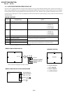
RM-Y906RM-Y906
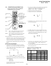
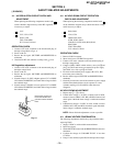
5-1. TV INPUT SUB CONTRAST ADJUSTMENT
(VPTR-GDRV)
1. Receive the NTSC color-bar (white 75%) signal.
2. Mode : Personal 1 or 2.
PICTURE : maximum
COLOR : minimum
BRIGHTNESS : center
TRINITONE : medium
ABL : CN801 pin 4open
SERVICE DATA VPTR GDRV : 37
3. Set to service mode.
4. Connect an oscilloscope between pin 7 of CN204 (A board)
and ground.
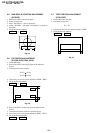
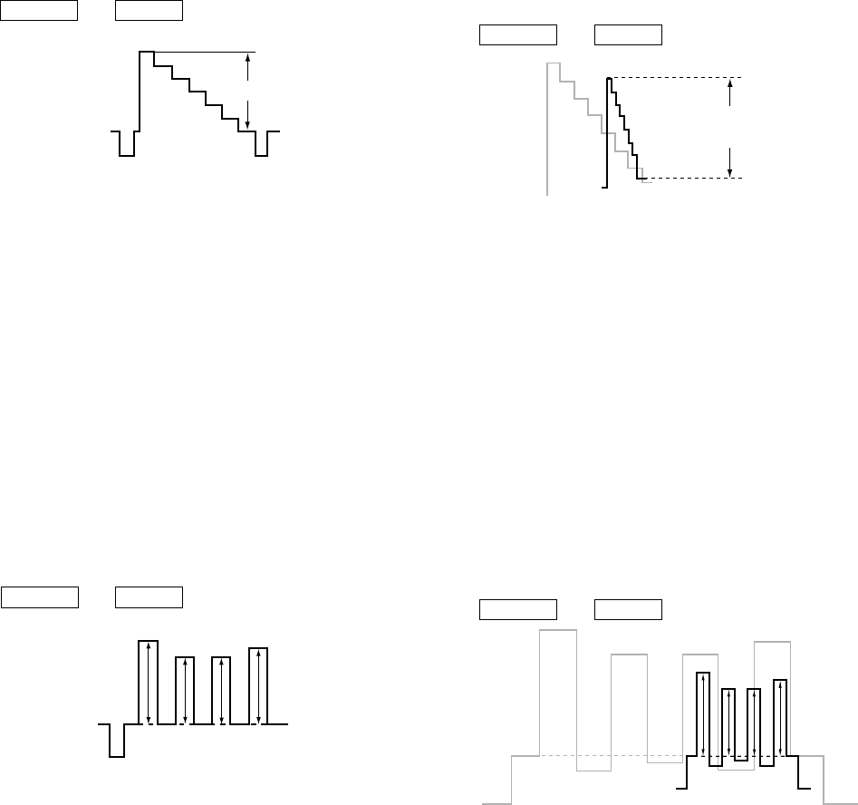
5. Select “ VPNT-GDRV”, and adjust so that the wave from
level is 1.80 ± 0.05Vp-p.
6. Write the data into memory.
MUTING n ENTER
White
1.80
± 0.05Vp-p
Black
Fig. 5-1
SECTION 5
CIRCUIT ADJUSTMENTS
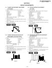
5-2. TV INPUT SUB-HUE AND SUB-COLOR
ADJUSTMENT (VPTR-SHUE, SCOL)
1. Receive the NTSC color-bar (white 75%) signal.
2. Mode : Personal 1 or 2.
PICTURE : maximum
COLOR : center
BRIGHTNESS : center
TRINITONE : medium
SERVICE DATA VPTR-SHUE : 32
SERVICE DATA VPTR-SCOL : 27
3. Set to service mode.
4. Connect an oscilloscope between pin 5 of CN204 (A board)
connecter and ground.
5. Select “ VPTR-SHUE, SCOL ”, and adjust them to have VB1
= VB4 and VB2 = VB3 in the waveform levels.
6. Write the data into memory.
MUTING n ENTER
VB1 VB2 VB3 VB4
Fig. 5-2
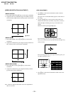
5-3. PIP SUB CONTRAST ADJUSTMENT
(SC-SYDR)
1. Receive the signal.
TV terminal (sub) : NTSC color-bar (white 75%)signal
VIDEO terminal (main) : no signal
2. PICTURE : maximum
COLOR : minimum
BRIGHTNESS : center
TRINITONE : medium
ABL : CN801 pin 4 open
SERVICE DATA : SC-SYDR
3. Set to service mode and set to PIP mode.
4. Connect an oscilloscope between pin 7 of CN204 (A board)
and ground.
5. Select “ SC-SYDR ”, and adjust so that the wave from level
is 1.65 ± 0.05Vp-p.
6. Write the data into memory.
MUTING n ENTER
Fig. 5-3
1.65 ± 0.05V
(PEDESTAL TO PEEK)
Fig. 5-4
5-4. PIP SUB-HUE, SUB-COLOR ADJUSTMENT
(SC-PHDR, SSCL)
1. Receive the signal.
TV terminal (sub) : NTSC color-bar (white 75%)signal
VIDEO terminal (main) : no signal
2. PICTURE : maximum
COLOR : minimum
BRIGHTNESS : center
TRINITONE : medium
ABL : CN801 pin 4 open
SERVICE DATA : SC-PHDR, SSCL
3. Set to service mode and set to PIP mode.
4. Connect an oscilloscope between pin 5 of CN204 (A board)
and ground.
5. Select “ SC-PHDR,SSCL ”, and adjust them to have
VB1=VB4 and VB2=VB3 in the wave from levels.
6. Write the data into memory.
MUTING n ENTER
VB1 VB2 VB3 VB4