


2-9
2. Preparation
CAST-AU4/B2521E
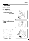
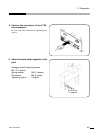
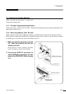
2. Connect the external signals to the USERl I/O connector by soldering.
Connect the wires to the corresponding pins of the USER I/O connector.
For the signal names and pin numbers of the respective pins, refer to the I/O connector input/output
specifications, Operation Manual (or Operation Manual of Full Open Programmable in the case of the
full open programmable specifications) of memory card (RK card).
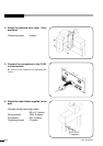
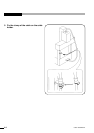
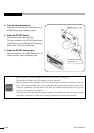
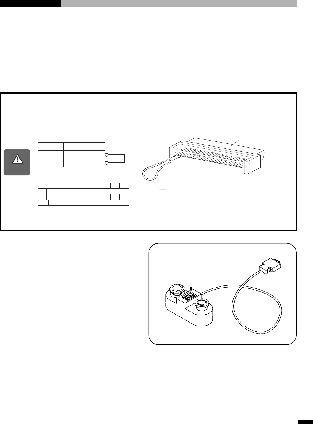
Precautions on operating the ROBOKIDS
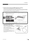
When using the RK card, connect the I/O connector supplied to the USER I/O connector SI1
(SYSRUN) of the machine as shown.
• USER I/O connector (supplied)
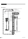
• Pin arrangement
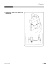
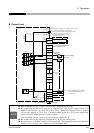
* Connect a jumper wire to the USER I/O connector (supplied), with soldering, attach the
connector supplied (accessory) to the connector.
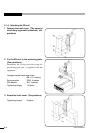
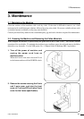
3. Controlling the program selector from
external location. (RK card only)
Connect the wires to the pins of the USER I/O
connector corresponding to the external
signals, by soldering. (I3 to I10)
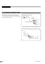
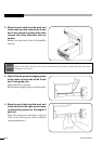
Set the first digit of the PROGRAM switch to
“F” when controlling the program selector
from external location.
If the second digit of the PROGRAM switch is
set to “F”, the application program is set to
external mode.
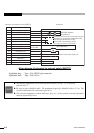
Caution
Pin No. Name
1
3
0 V
SYSRUN
2468
~
30 32 34
13579
~
29 31 33
36 38 40 42
~
64
66 68
35 37 39
41
~
63
65
67
Connection
Pin No.1
Pin No.3
Connect a jumper wire with soldering
(AWG30 or equivalent)
USER I/O connector
(supplied)
PROGRAM switch
Controlling the program selector
from external location • • • Set to “F”