


5-7
5-8
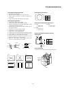
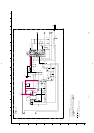
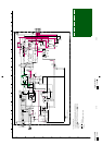
5-4. SCHEMATIC DIAGRAMS AND PRINTED
WIRING BOARDS
Note:
• All capacitors are in µF unless otherwise noted. (pF: µµF)
Capacitors without voltage indication are all 50 V.
• Indication of resistance, which does not have one for rating
electrical power, is as follows.
Pitch: 5 mm
Rating electrical power 1/4 W (CHIP : 1/10 W)
• All resistors are in ohms.
•
f : nonflammable resistor.
•
F : fusible resistor.
•
f : internal component.
•
p : panel designation, and adjustment for repair.
• All variable and adjustable resistors have characteristic curve B,
unless otherwise noted.
•
e : earth-ground.
•
E : earth-chassis.
• All voltages are in V.
• Readings are taken with a 10 M digital multimeter.
• Readings are taken with a color-bar signal input.
• Voltage variations may be noted due to normal production
tolerances.
•
*
: Can not be measured.
• Circled numbers are waveform references.
•
s : B + bus.
•
S : B – bus.
• When replacing components identified by
], make the
necessary adjustments indicated. (See page 3-1)
• When replacing the part in below table, be sure to perform the
related adjustment.
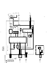
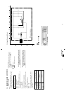
• Divided circuit diagram
One sheet of D board circuit diagram is divided into four
sheets, each having the code D-a to D-d . For example, the
destination ab1 on the D-a sheet is connected to ab1 on the
D-b sheet.
b
1
a
Ref. No.
Circuit diagram division code
Note: The components identified by shading and mark
0 are critical for safety. Replace only with part
number specified.
Note: Les composants identifiés par un tramé et une
marque 0 sont critiques pour la sécurité. Ne les
remplacer que par une pièce portant le numéro
spécifié.
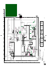
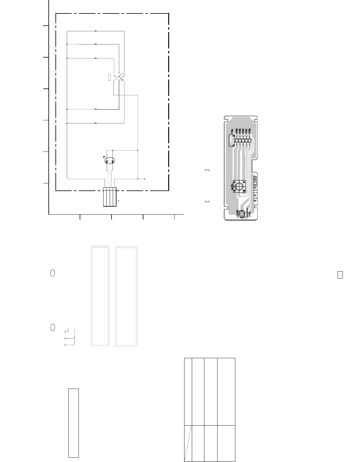
Schematic diagram
Board
ll
ll
l
H
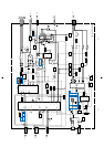
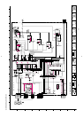
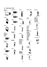
(1) Schematic Diagram of H Board
1
A
B
C
D
2
765
43
1
2
3
4
P701
4P
MENU
GND
ORANGE/LED
GREEN/LED
R709
17.4k
1%
R705
6.19k
R702
10.2k
1%
H
(USER CONTROL)
6
3
5
4
2
R706
3.83k
R701
2.15k
1%
1
LED701
LT6463-23-D51
SW701
B-SS3562<NH.>-H..-EPS05
(POWER)
TO D-a BOARD
CN901
MENU
(h)
USER CONTROL
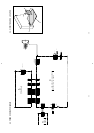
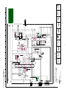
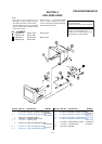
HV Regulator
Circuit Check
HV Hold-down
Circuit Check
Beam Current
Protector Circuit
Check
Part Replaced (])
D board IC502, T501 (FBT)
D board D538, R521,
T501 (FBT)
D board IC901, R949,
T501 (FBT)