


5
GB
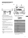
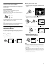
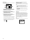
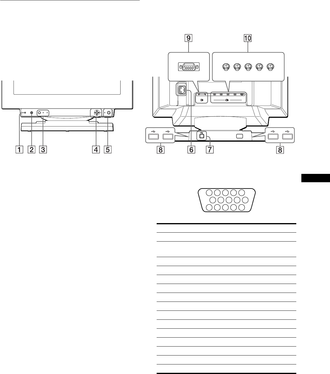
Identifying parts and controls
See the pages in parentheses for further details.
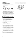
1 RESET (reset) button (page 16)
This button resets the adjustments to the factory settings.
2 ASC (auto sizing and centering) button (page 9)
This button automatically adjusts the size and centering of the
picture.
3 INPUT button and HD15 / BNC indicators (page 9)
This button selects the HD15 or BNC video input signal.
Each time you press this button, the input signal and
corresponding indicator alternate.
4 Joystick (page 11)
The joystick is used to display the menu and make
adjustments to the monitor, including brightness and contrast
adjustments.
5 1 (power) switch and indicator (pages 7, 16, 20)
This button turns the monitor on and off. The power indicator
lights up in green when the monitor is turned on, and either
flashes in green and orange, or lights up in orange when the
monitor is in power saving mode.
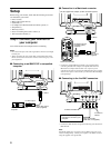
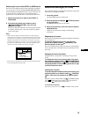
6 AC IN connector (page 7)
This connector provides AC power to the monitor.
7 USB (universal serial bus) upstream connector
(page 8)
Use this connector to link the monitor to a USB compliant
computer.
8 USB (universal serial bus) downstream connectors
(page 8)
Use these connectors to link USB peripheral devices to the
monitor.
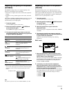
9 Video input 1 connector (HD15) (page 6)
This connector inputs RGB video signals (0.700 Vp-p,
positive) and sync signals.
* DDC (Display Data Channel) is a standard of VESA.
q; Video input 2 connector (BNC) (page 6)
This connector inputs RGB video signals (0.700 Vp-p,
positive) and sync signals.
RESET ASC INPUT MENUHD15 BNC
AC IN
(HD15)
1
(BNC)
RGBHDVD
2
Rear
rear side
forward side
forward side
rear side
Front
Pin No. Signal
1Red
2 Green
(Composite Sync on Green)
3Blue
4 ID (Ground)
5 DDC Ground*
6 Red Ground
7 Green Ground
8 Blue Ground
9 DDC + 5V*
10 Ground
11 ID (Ground)
12 Bi-Directional Data (SDA)*
13 H. Sync
14 V. Sync
15 Data Clock (SCL)*
5 4 3 2
1
678910
1112131415