


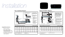

Floor Installation Diagram
Installation
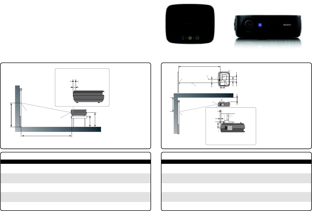
Ceiling Installation Diagram
Ceiling Installation (Front Projection)
SS 40 60 80 100 120 150 180 200 250 300
aN1220 1820 2430 3040 3640 4550 5470 6070 7590 9110
(48•1/8) (71•3/4) (95•3/4) (119•3/4) (143•3/8) (179•1/4) (215•1/2) (239•1/8) (298•7/8) (358•3/4)
aM1440 2090 2790 3490 4180 5230 6270 6970 8710 10450
(55•1/8) (82•3/8) (109•7/8) (137•1/2) (164•5/8) (206) (247) (274•1/2) (343) (411•1/2)
x b+260 b+362 b+463 b+565 b+667 b+819 b+971 b+1073 b+1327 b+1581
(b+10•1/4) (b+14•3/8) (b+18•1/4) (b+22•1/4) (b+26•3/8) (b+32•1/4) (b+38•1/4) (b+42•1/4) (b+52•1/4) (b+62•1/4)
• a'(N)={(SS*18.56/0.6299+3.3}*1.03 • a'(M)={(SS*22.61/0.6299+3.3}*0.97
• x=b+(SS/0.6299*3.2+57.0)
x
Center of the
screen
Center of the lens
a’
b
Ceiling
Distance between the front of the cabinet and
the hole for mounting a projector suspension
support (front)
Front of the
cabinet
Center of the lens
13.7(
9
/
16
)
This section describes the examples
of installing the projector on the
ceiling. When installing the projector
on the ceiling, use a Projector
Suspension Support recommended
by Sony. For ceiling installation,
ask for qualified Sony personnel.
The alphabetical letters in the
illustration indicate the distances
below.
a’: distance between the hole (front) for
mounting a projector suspension
support on bottom surface of this
projector and the center of the
screen
b: distance between the hole (front) for
mounting a projector suspension
support on bottom surface of this
projector and the ceiling
x: distance between the ceiling and
the center of the screen
Unit: mm (inches)
41(1
5
/
8
)
Holes for mounting a projector
suspension support
57
(2
1
/
4
)
Center of the Projector
Hole for mounting a
projector suspension
support (front)
Center of the screen
Center of the lens
83(3
3
/
8
)
104.5
(4
1
/
8
)
55(2
1
/
4
)
102.8(4
1
/
8
)
Center of the lens
Wall
x
Center of the
screen
Center of the lens
a
c
b
Floor
Distance between the front of the
cabinet and the center of the lens
Front of the
cabinet
Front of the lens
13.7(
9
/
16
)
This section describes
the examples of installing
the projector on a desk,
etc.
The alphabetical letters in
the illustration indicate the
distances below.
a: distance between the
screen and the center
of the lens
b: distance between the
floor and the center of
the lens
c: distance between the
floor and the bottom
of the adjusters of
the projector
x: distance between the
floor and the center of
the screen (free)
Unit: mm (inches)
Unit: mm (inches)Floor Installation (Front Projection)
SS 40 60 80 100 120 150 180 200 250 300
aN1190 1800 2400 3010 3620 4530 5440 6040 7560 9080
(46•7/8) (70•7/8) (94•1/2) (118•17/32) (142•5/8) (178•3/8) (214•1/4) (237•7/8) (297•3/4) (357•5/8)
aM1370 2070 2760 3460 4160 5200 6240 6940 8680 10420
(54) (81•5/8) (108•3/4) (136•1/4) (163•7/8) (204•3/4) (245•3/4) (273•3/8) (341•7/8) (410•3/8)
b x-203 x-305 x-406 x-508 x-610 x-762 x-914 x-1016 x-1270 x-1524
(x-8) (x-12•1/8) (x-16) (x-20) (x-24•1/8) (x-30) (x-36) (x-40) (x-50) (x-60)
c x-271 x-372 x-474 x-576 x-677 x-830 x-982 x-1084 x-1338 x-1592
(x-10•3/4) (x-14•3/4) (x-18•3/4) (x-22•3/4) (x-26•3/4) (x-32•3/4) (x-38•3/4) (x-42•3/4) (x-52•3/4) (x-62•3/4)
• a(N) = {(SS * 18.56/0.6299)-24.0} * 1.03 • b = x-(SS/0.6299 * 3.2)
• a(M) = {(SS * 22.61/0.6299)-24.0} * 0.97 • c = x-(SS/0.6299 * 3.2+67.6)
Unit: mm (inches)
b Free
Supplied Accessories
• Remote Commander
• Lithium Battery CR2025
• HD D-sub 15 pin Cable, Carrying
Case and Security Label
• Operating Instructions (CD-ROM)
• Quick Reference Manual and
Safety Regulations